
Installation Instructions, 200 A Owner manual

16 Rockwell Automation Publication 1608P-IN004A-EN-P - September 2013
Chapter 4 Applying Power and Operation
HC-DySC System Operation
System Description
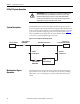
The HC-DySC system consists of the DySC dynamic voltage sag correction
electronics together with an integral maintenance bypass switch. In the Normal
mode of operation the raw utility power is routed through the DySC electronics
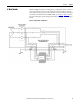
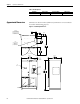
to protect the loads from voltage sags and momentary interruptions. Figure 8
shows a simplified one-line diagram for the system. Neutral and Ground
connections are passed straight through to the loads.
Figure 8 - One Line Diagram of the HC-DySC System
Maintenance Bypass
Operation
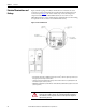
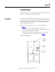
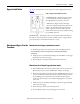
The HC-DySC has an integral maintenance bypass switch. The maintenance
bypass switch is used to avoid power interruptions to the critical loads during
maintenance or service. The bypass is a 3 position make-before-break rotary
switch.
SHOCK HAZARD: Dangerous voltages are present within the HC-DySC System.
The unit should never be operated with the enclosure door open except by
qualified and authorized personnel who are trained and familiar with the
operation of the unit and the location of components and voltages. Failure to
comply with this warning could result in injury or death.
L1, L2, L3 X1, X2 , X3
DySC
EL EC T RONI CS
OUTPUT TO
PROTECTED LOADS
CBI CIRCUIT
BREAKER
OUTPUT
CONTACTS
INPUT
CONTACTS
BYPASS CONTACTSUTILITY INPUT
CBA CIRCUIT
BREAKER