
Installation Instructions, 200 A Owner manual

Rockwell Automation Publication 1608P-UM004A-EN-P - September 2013 11
Installation Chapter 2
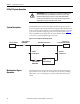
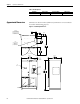
4- Wire Models
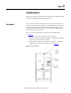
Bulletin 1608P part numbers containing V4 are configured for 4-wire source (L1,
L2, L3, N) and either 3-wire or 4-wire loads. The source N conductor must be
connected for proper operation of these models. Connect both input and output
N conductors to the bus bar labeled NEUTRAL (See Figure 5
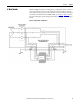
). Figure 4 shows
the 4-wire HC-DySC system wiring schematically, including the internal Bypass
Switch.
Figure 4 - HC-DySC 4-Wire Configuration.
HC-DySC