User Manual Bulletin 1608N MiniDySC® Dynamic Sag Corrector Single Phase Voltage Sag Correction 2...6 Amps (250...
Important User Information Solid-state equipment has operational characteristics differing from those of electromechanical equipment. Safety Guidelines for the Application, Installation and Maintenance of Solid State Controls (publication SGI-1.1 available from your local Rockwell Automation sales office or online at http://www.rockwellautomation.com/literature/) describes some important differences between solid-state equipment and hard-wired electromechanical devices.
Table of Contents Important User Information . . . . . . . . . . . . . . . . . . . . . . . . . . . . . . . . . . . . . . . . 2 Additional Resources . . . . . . . . . . . . . . . . . . . . . . . . . . . . . . . . . . . . . . . . . . . . . . . 2 Ch 1 - Installation Installation Check List . . . . . . . . . . . . . . . . . . . . . . . . . . . . . . . . . . . . . . . . . . . . . 5 Inspecting and Unpacking . . . . . . . . . . . . . . . . . . . . . . . . . . . . . . . . . . . . . . . . . .
Table of Contents Notes: 4 Rockwell Automation Publication 1608N-UM001B-EN-P - May 2014
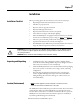
Chapter 1 Installation Installation Check List Before proceeding, please take a few minutes to review the necessary steps: • All packing materials and restraints have been removed • All cables are properly routed • All power cables are properly terminated • Properly installed ground connector • Properly terminated neutral connection (if required) • Clean, dust-free work space with adequate lighting • Mount the MiniDySC in an upright orientation with at least 2” (50 mm) clearance above and below for prope
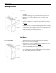
Chapter 1 Installation Mounting Instructions DIN Rail Mount Figure 1 - DIN Rail Mounting 1. Mount on a 35 x 7.5 mm DIN rail that conforms to the EN 50022 standard. 2. The DIN mounting clips come pre-assembled to the back of the unit. 3. Hook the top edge of the mounting clips over the top flange of the DIN rail. 4. Pivot the MiniDySC down until the unit latches to the DIN rail. 5.
Chapter 2 Operation Ground Connection • • Connect the safety ground (earth) conductor to the #8-32 (4.2mm dia.) ground stud (Refer to Figure 3 on page 8 or Figure 4 on page 8). Torque to 20 lb-in (2.3 N-m) Note: The MiniDySC must be safety grounded according to the National Electrical Code. All local, state, and federal regulations applicable to the installation of electrical systems apply.
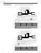
Chapter 2 Operation Connection Diagrams Figure 3 - 120, 220,230, 240 Volt, 1 Phase, Line-to-Neutral Connection Diagram C NC NO X1 L1 N Input A.C. 1 SW1 Neutral 2 X1 F1 Ground Ground LOAD L1 Neutral 1. User-supplied service disconnect (SW1). MiniDySC must be supplied through a single pole switch in the "hot" line, with voltage and current ratings greater than or equal to the MiniDySC ratings. 2. User-supplied fuse (F1). AC input must be fused. See Table 1 for recommended fuse.
Operation Alarm Contact Connections • • Chapter 2 The alarm contact will change states during any alarm condition. When the alarm condition has cleared, the alarm relay will return to its normal state. Terminal block pin numbers and Alarm contact ratings are shown in Figure 5 Operation is as follows: – Normal Line Condition: pin 1 connects to pin 3. – Alarm Condition: pin 1 connects to pin 2. – Power Off Condition: pin 1 connects to pin 2.
Chapter 2 Operation Alarm LED Flash Sequence Alarm Codes While the MiniDySC is in the alarm state due to a non-fatal alarm, the amber LED will flash the alarm code sequence at 1Hz where the number of flashes equals the alarm code. There is a two-second delay, after which the code will repeat if the error condition persists. This group of alarms are those that the user can act to correct, such as an overload or input over-voltage. Some alarms cannot be corrected by user action.
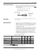
Chapter 3 Specifications and Dimensions Technical Specifications Table 5 - Technical Specifications – MiniDySC (2...6 Amps) Electrical Input/Output (Normal Mode—Static Switch) Connection Configuration Series-connected with load.
Chapter 3 Specifications and Dimensions Approximate Dimensions Rating (VA) 250 500 750 250 500 750 Dimensions Dimensions - H x W x D in. [mm] Standard Run-time (SR) 8.3 x 3.4 x 6.3 [210.8 x 86.4 x 160] 9.3 x 3.4 x 7.8 [236.2 x 86.4 x 198.1] 9.3 x 3.4 x 7.8 [236.2 x 86.4 x 198.1] Extended Run-time (ER) 8.3 x 5.8 x 6.3 [210.8 x 147.3 x 160] 9.3 x 5.8 x 7.8 [236.2 x 147.3 x 198.1] 9.3 x 5.8 x 7.8 [236.2 x 147.3 x 198.1] Weight - lbs. [kg] 4.8 [2.18] 6.3 [2.86] 6.7 [3.04] 8.0 [3.63] 9.5 [4.31] 10.2 [4.
Rockwell Automation Support Rockwell Automation provides technical information on the Web to assist you in using its products. At http://www.rockwellautomation.com/support, you can find technical manuals, technical and application notes, sample code and links to software service packs, and a MySupport feature that you can customize to make the best use of these tools. You can also visit our Knowledgebase at http://www.rockwellautomation.