
User Manual, 12-50 Amp Owner's manual


Rockwell Automation Publication 1608N-UM002B-EN-P - May 2014 7
Installation Chapter 1
Mounting Dimensions
12 A -25A SR/ER and 50A SR MiniDySC
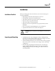
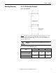
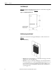
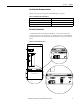
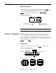
Figure 1 - Top Keyed MiniDySC
Figure 1 shows the top keyed and bottom hole dimensions for the 12 A, 25 A
(Standard and Extended ride through SR/ER) and 50 A SR MiniDySC. To
access the lower mounting holes, four cover screws (two on each side of lower
cover) must be removed.
Table 2 - 12/25/50 Amp SR/ER Mounting Dimensions
ATTENTION: DO NOT REMOVE THE TOP COVER. WARRANTY WILL BE VOIDED IF IT
IS REMOVED.
Rating
ABC
in.
[mm]
12 A
7.0
[177.8]
17.95
[455.9]
7.0
[177.8]
25 A SR
25 A ER
12.0
[304.8]
17.95
[455.9]
13.75
[349.3]
50 A SR
Lower Mounting Holes Located
Under Wiring Access Cover
Vent holes in both sides.
Maintain 3 in. clearance
for proper cooling.
B
A
C