
User Manual, 12-50 Amp Owner's manual


10 Rockwell Automation Publication 1608N-UM002B-EN-P - May 2014
Chapter 1 Installation
Accessing Terminations
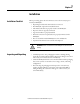
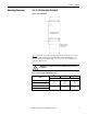
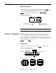
Three knockout holes are provided for conduit entry, as shown in Figure 5. Take
care to avoid dropping any metal filings inside the enclosure. Metallic
contamination will void the product warranty. See Figure 8
, Figure 9, and
Figure 10
for input/output terminal locations.
Figure 5 - Knockout Hole Locations
L-N Versus L-L Configuration
MiniDySC terminals are labeled in accordance with the AC input source type.
Bulletin 1608N part numbers containing V2 are configured for single-phase
line-to-neutral (phase-to-neutral) input, with input terminals labeled L1 and N. Part
numbers containing V1 are configured for line-to-line (phase-to-phase) input, with
input terminals labeled L1 and L2. Select the correct connection diagram between
Figure 6
(L-N) and Figure 7 (L-L).
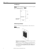
Line to Neutral
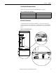
MiniDySC L-N models must be connected as in Figure 6 to operate properly.
Figure 6 - Line to Neutral Configuration
IMPORTANT
Metallic Particles inside the enclosure will void the warranty
COMMUNICATIONS
.89 [22.6mm] DIAMETER EKO
2X INPUT AND OUTPUT
AC CONNECTIONS.
.89 [22.6mm] DIAMETER EKO
GR
X1
N
N
L1
GR
L1
N
N
X1
GR
X1NNL1
INPUT SOURCE
User Supplied
Circuit Breaker
L1
N
GND
GROUND
STUD
OUTPUT TO LOADS
X1
N
GND
X1NNL1
L-N
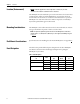
25A ER 50A SR/ER12A-25A SR
Terminal Block Configurations