User Manual Bulletin 1608N MiniDySC® Dynamic Sag Corrector Single Phase Voltage Sag Correction 12...
Important User Information Read this document and the documents listed in the additional resources section about installation, configuration, and operation of this equipment before you install, configure, operate, or maintain this product. Users are required to familiarize themselves with installation and wiring instructions in addition to requirements of all applicable codes, laws, and standards.
Table of Contents Important User Information . . . . . . . . . . . . . . . . . . . . . . . . . . . . . . . . . . . . . . . . 2 Additional Resources . . . . . . . . . . . . . . . . . . . . . . . . . . . . . . . . . . . . . . . . . . . . . . . 2 Ch 1 - Installation Installation Check List . . . . . . . . . . . . . . . . . . . . . . . . . . . . . . . . . . . . . . . . . . . . . 5 Inspecting and Unpacking . . . . . . . . . . . . . . . . . . . . . . . . . . . . . . . . . . . . . . . . . .
Table of Contents Notes: 4 Rockwell Automation Publication 1608N-UM002B-EN-P - May 2014
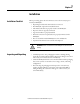
Chapter 1 Installation Installation Check List Before proceeding, please take a few minutes to review the necessary steps to install your MiniDySC. • All packing materials and restraints have been removed. • The MiniDySC is placed in its installed location. • All conduits and cables are properly routed to the MiniDySC. • All power cables are properly terminated. • A ground conductor is properly installed. • If neutral connection is required that it is properly terminated on the MiniDySC.
Chapter 1 Installation Location (Environment) NOTICE: Install this equipment in an indoor temperature-controlled area, free from condensation and conductive contaminants such as carbon dust. The MiniDySC must be installed in a protected environment. The location must provide adequate airflow around the MiniDySC in an atmosphere free from excessive dust, corrosive fumes, or conductive contaminants.
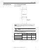
Installation Mounting Dimensions Chapter 1 12 A -25 A SR/ER and 50 A SR MiniDySC Figure 1 - Top Keyed MiniDySC A B Lower Mounting Holes Located Under Wiring Access Cover Vent holes in both sides. Maintain 3 in. clearance for proper cooling. C Figure 1 shows the top keyed and bottom hole dimensions for the 12 A, 25 A (Standard and Extended ride through SR/ER) and 50 A SR MiniDySC. To access the lower mounting holes, four cover screws (two on each side of lower cover) must be removed.
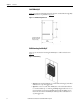
Chapter 1 Installation 50 A ER MiniDySC Figure 2 provides mounting dimensions for the 50 A extended ride through (ER). Key slot dimensions are provided in Figure 14. Figure 2 - 50 A ER Mounting Dimensions 16.00 (406.40) Vent holes in both sides. Maintain 3 in. clearance for proper cooling. 17.52 (444.
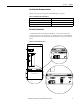
Installation Chapter 1 Circuit Breaker Recommendations Branch circuit protection upstream of the MiniDySC is required Table 3 - Circuit Breaker Recommendations Rated MiniDySC (Amps) Maximum Rated Breaker (Amps) 12 15 25 35 50 70 Electrical Terminations A qualified electrician must install the MiniDySC. To access the connections, remove the four screws on the bottom cover and lift off the cover. The MiniDySC is furnished with one of the terminal block configurations as shown in the figures below.
Chapter 1 Installation Accessing Terminations Three knockout holes are provided for conduit entry, as shown in Figure 5. Take care to avoid dropping any metal filings inside the enclosure. Metallic contamination will void the product warranty. See Figure 8, Figure 9, and Figure 10 for input/output terminal locations. Figure 5 - Knockout Hole Locations COMMUNICATIONS .89 [22.6mm] DIAMETER EKO IMPORTANT L-N Versus L-L Configuration 2X INPUT AND OUTPUT AC CONNECTIONS. .89 [22.
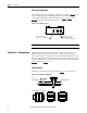
Installation Chapter 1 Line to Line MiniDySC L-L models must be connected as in Figure 7 to operate properly. Figure 7 - Line to Line Configuration L1 L2 X2 X1 L-L User Supplied Circuit Breaker INPUT SOURCE OUTPUT TO LOADS L1 X1 L2 X2 GND GND GROUND STUD Terminal Block Configurations L1 L2 X1 X2 GR 12A-25A SR Completing Terminations L1 X1 L2 X2 X1 L2 X2 L1 GR GR 25A ER 50A SR/ER Output terminals are marked X1 and N or X1 and X2.
Chapter 1 Installation Figure 9 - 25 Amp Extended Ride Through (ER) INPUT/OUTPUT TERMINAL RATING: 22-8 AWG (0.5-6mm2) TORQUE: 7.1-8.9 lb-in. (0.8-1.0 N-m) WIRE STRIP LENGTH: .47" [12mm] FUSE TERMINAL BLOCK LINE TO LINE LINE TO NEUTRAL OR L1-L2-X1-X2-GR L1-N-N-X1-GR 1/4-20 GROUND STUD TORQUE: 65 in-lb. (7.3 N-m) Figure 10 - 50 Amp Standard/Extended Ride-through (SR/ER) INPUT/OUTPUT TERMINAL RATING: 16-0 AWG (1.5 - 50 mm2) TORQUE: 24.3-26.1 lb-in. (2.7 - 2.9 N-m) WIRE STRIP LENGTH: .
Installation Chapter 1 Figure 11 - Communications (Dry Contacts) CUSTOMER COMMUNICATIONS CONNECTION AREA. 24-12 AWG (0.2-2.5mm2) TORQUE: 5.0 lb-in (0.
Chapter 1 Installation Notes: 14 Rockwell Automation Publication 1608N-UM002B-EN-P - May 2014
Chapter 2 Operation The MiniDySC is fully automatic and requires no user intervention for normal operation. 1. Before applying power to the MiniDySC, ensure that all input/output wiring including grounding has been completed and that the wiring access cover is on and screwed down. Applying Power 2. The load should be connected prior to performing system checks. 3. Apply power, note that the green “Normal” LED will be illuminated. 4.
Chapter 2 Operation Communications 16 Two relay contacts indicate MiniDySC status. The contacts are form A and close upon occurrence of the named event: (a) OUTPUT OK, when output voltage remains between 87…110% of nominal value; and (b) a system ALARM event. The relay contact ratings are 24V DC at 1 A. The communications wiring area detail is shown in Figure 11. A barrier plate prevents contact between communications wiring and power wiring.
Chapter 3 Specifications and Dimensions Table 5 - Technical Specifications – MiniDySC (12…50 Amps) Electrical Input/Output (Normal Mode—Static Switch) Connection Configuration Series-connected with load. Under normal line condition, the static switch passes utility voltage directly to the load Standard Input Voltage DySC 1Phase: 120, 208, 220, 230, 240V Voltage Range ± 10% Output Current (Static Switch) 0...
Chapter 3 Specifications and Dimensions Approximate Dimensions Dimensions HxWxD in. [mm] Standard Run-time (SR) 22 x 10 x 4 [550.8 x 254 x 101.6] 21 x 19 x 4 [533.4 x 482.6 x 101.6] Extended Run-time (ER) 21 x 19 x 4 [533.4 x 482.6 x 101.6] 21 x 19 x 7 [533.4 x 482.6 x 177.8] Rating (A) 12, 25 50 25 50 Weight lbs.[kg] 18.6 [8.44] 34.5 [15.5] 32.5 [14.7] 51.5 [23.4] Dimensions in inches [mm]. Dimensions are not intended to be used for manufacturing purposes. Figure 12 - 12 Amp and 25 Amp SR Dimensions .
Specifications and Dimensions Chapter 3 Figure 13 - 25 Amp ER /50 Amp SR Dimensions R.14 3.59 16.02 406.83 .51 13 .350 8.89 A 12.00 304.80 UPPER MOUNTING 3.56 90.51 DETAIL A MOUNTING KEYHOLE 2 PLACES 21.14 536.97 17.95 455.93 VERTICAL MOUNTING 13.75 349.25 LOWER MOUNTING LOWER MOUNTING HOLES LOCATED UNDER ACCESS COVER. SEE DETAIL B B 2X INPUT AND OUTPUT AC CONNECTIONS. .89 [22.6mm] DIAMETER EKO COMMUNICATIONS .89 [22.6mm] DIAMETER EKO 1.31 33.27 3.08 78.32 11.93 303.11 DETAIL B 4.83 122.
Chapter 3 Specifications and Dimensions Figure 14 - 50 Amp ER Dimensions .28 7.21 .51 13 .350 8.89 DETAIL A MOUNTING KEYHOLE 2 PLACES 19.02 483.03 OVERALL 7.06 179.44 17.52 444.93 MOUNTING A 20.27 514.74 16.00 406.40 MOUNTING 2X .281 MOUNTING HOLES COMMUNICATIONS .89 [22.6mm] DIAMETER EKO 2X INPUT AND OUTPUT AC CONNECTIONS. .89 [22.6mm] DIAMETER EKO 4.81 122.28 11.93 303.11 20 Rockwell Automation Publication 1608N-UM002B-EN-P - May 2014 3.08 78.32 4.83 122.
Appendix A Special Instructions for Model 1608N-012A120V2S-R Rack-Mount MiniDySC MiniDySC model 1608N-012A120V2S-R is configured to protect line-corded loads in a 19-inch IT rack environment. Amended specifications and dimensions for this model are listed in Table 6. All other specifications, including environmental and certifications, are as listed in Table 5. This model does not include alarm contacts. LED indicators are frontfacing.
Appendix A Table 6 - Technical Specifications - Rack-Mount MiniDySC, PN 1608N-012A120V2S-R Electrical Input Voltage (nominal) 1 Phase (L-N), 120V ±10% Output Current 12 A Upstream Circuit Breaker (required) Rating 15 A Mechanical Mounting Hardware Kit (included) Weight (2) Mounting Brackets (see Figure 16) (8) Cage Nut, 10-32 (16) Screw, 3/8 in. Phillips, 10-32, with lock washer (8) Screw, 3/4 in. slotted Truss, 10-32 22.
Rockwell Automation Support Rockwell Automation provides technical information on the Web to assist you in using its products. At http://www.rockwellautomation.com/support, you can find technical manuals, technical and application notes, sample code and links to software service packs, and a MySupport feature that you can customize to make the best use of these tools. You can also visit our Knowledgebase at http://www.rockwellautomation.