
User Manual, 800 Amp - 208V Owner's manual


Rockwell Automation Publication 1608M-UM003A-EN-P - December 2013 21
Chapter 3
Communications
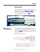
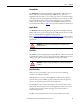
Communication connections enter through the top of the switchboard enclosure
marked CUSTOMER I/O PLATE in Figure 1
, Figure 2, or Figure 3. This plate
can be fitted as needed for conduit entry. Communications terminals are
described on the following pages. The ports are located at the top of the left
Automatic Bypass Switchboard and are shown in Figure 14
. Use RJ45 port
number 5 for the communications connection.
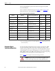
Figure 14 - Customer I/O terminals
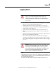
Remote Diagnostics
(TB1 Customer Contacts)
Customer-accessible dry contact-closures are available for relaying the state of the
circuit breakers and the state of the MegaDySC system. Connect to terminal
block TB1, located at the top of the left compartment of the Automatic Bypass
Switchboard. See Figure 15
for connection details. The contact ratings are: 10A
@ 240VAC Resistive, 7A @ 240VAC Inductive, 10A @ 28V DC resistive and
8A @ 24V DC inductive.
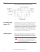
Figure 15 - Schematic of Customer Dry Contacts
• CBB Closed (CR3A) – Contact is closed when the bypass circuit breaker
(CBB) is closed. Contact is open when CBB is open.
• CBI Closed (CR4A) - Contact is closed when the input circuit breaker
(CBI) is closed. Contact is open when CBI is open.