
User Manual, 800 Amp - 208V Owner's manual

20 Rockwell Automation Publication 1608M-UM003A-EN-P - December 2013
Chapter 2 Installation
MegaDySC System Installation Connections Checklist
• Connect the Automatic Bypass Switchboard ground bus to an earth
ground in accordance with the National Electrical Code and local codes.
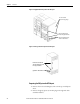
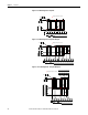
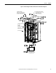
• Connect the AC input (line) conductors to the terminals labeled “R in”,
“Sin”, and “T in”. The set is labeled “UTILITY INPUT”. See Figure 13
.
• Connect the AC output (load) conductors to the terminals labeled “R
out”, “S out” and “T out”. The set is labeled “PROTECTED LOAD”. See
Figure 13
.
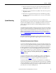
• For 4-wire models only: connect input and output Neutral (N) conductors
to the NEUTRAL bus bar. The input N connection is required for proper
operation of 4-wire models.
• Check all electrical terminations for properly torqued connections.
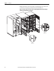
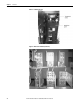
• For i-Sense and MegaDySC communications: connect an Ethernet cable
to the Ethernet switch located in the upper left compartment of the
Automatic Bypass Switchboard. Refer to Chapter 3
- Communications on
page 21 for details.
• For remote status indication via dry contacts, connect to the “TB1”
terminal block located in the upper left compartment of the Automatic
Bypass Switchboard. Refer to Chapter 3
- Communications on page 21 for
details.