
User Manual, 800 - 2400 A User guide


Rockwell Automation Publication 1608M-UM002A-EN-P - September 2013 9
Installation Chapter 2
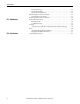
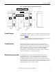
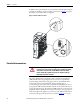
Figure 2 - Typical System Layout, Front View (800A ER model shown)
System Clearance
The MegaDySC and ER cabinet doors are hinged on the left, and clearance must
be given to allow the door to swing open 90 degrees to the front of the enclosure,
as shown in Figure 1
.
Clearance for the Automatic Bypass switchboard should allow the door to swing
(left side hinged) open 90 degrees to the front of its enclosure.
System Mounting
The MegaDySC is floor mounted, and should be secured using the 0.63"
diameter mounting holes provided at the bottom of each section. Since each
MegaDySC cabinet is provided with interconnecting cables to the Automatic
Bypass switchboard, proper arrangement is critical. Follow the MegaDySC
cabinet arrangement label located on the front of the Automatic Bypass
switchboard for proper unit arrangement. MegaDySC cabinets are identified
with a label located just above the main door handle.
Mechanical Interconnections
The MegaDySC and Switchboard cabinets should be bolted together for
maximum stability. 3/8” x 1" bolts with 1" flat washer and lock washer are
provided for this purpose (tighten to 25 lb-ft [42.4 N-m]). The bolts pass
through the right side of each cabinet and screw into the weld nuts in the next
enclosure in the lineup. There are three holes vertically aligned along the front
edge and another three holes along the rear edge. The three rear bolts are optional
and installation will require access from the rear.
LH1 RH1
ER ER
Bypass Switchboard
TB1 Access Comm. Ports Access