
User Manual, 800 - 2400 A User guide


8 Rockwell Automation Publication 1608M-UM002A-EN-P - September 2013
Chapter 2 Installation
System Orientation and
Layout
The required layout places the MegaDySC enclosures on the right-hand (RH)
and left-hand (LH) sides of the Automatic Bypass Switchboard when viewed
from the front. Each MegaDySC enclosure is labeled with its required position in
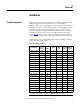
the lineup. System components are labeled as in Table 2
.
Table 2 - System Components Layout
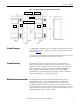
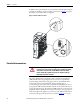
The enclosures must be mounted so that they abut tightly with no gap between
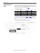
the enclosures. Typical layout is shown in Figure 1
and Figure 2. The “ER”
components shown in the figures are included only with ER models, not with SR
models.
Figure 1 - Typical System Layout, Top View (800A ER model shown)
Current Rating (A) LH3 LH2 LH1 Switchboard RH1 RH2 RH3
800
■■■
1200
■■ ■ ■
1600
■■ ■ ■■
2000
■■■ ■ ■■
2400
■■■ ■ ■
■
■
Optional TB1 & Comm. Port
Conduit Entry in this area