
User Manual, 800 - 2400 A User guide


14 Rockwell Automation Publication 1608M-UM002A-EN-P - September 2013
Chapter 3 Communications
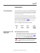
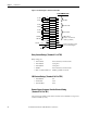
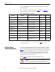
Figure 6 - Schematic Diagram—Customer Contacts (TB1)
Relay Contact Ratings (Terminals 1-9 of TB1)
Relays ratings are:
• 110-277VAC 10A continuous, 16A short time
• 110-120VAC 1/3 hp max
• 220-250VAC 1/2 hp max
• 28VDC 10A continuous, 16A short time
• Min. recommended load: 100mA @ 5VDC or 0.5 W
CBB Contact Ratings (Terminals 10-12 of TB1)
• 110-600VAC 6A
• 24-48 VDC 2.5A
• 125-250 VDC 0.5A
Remote Bypass Customer-Provided Contact Rating
(Terminals 14-15 of TB1)
The customer-provided contact must be rated for at least 120VAC. Coil power is
2 VA at 120 VAC (17 mA)
15
14
13
12
11
10
9
8
7
6
5
4
3
2
1
15
14
13
12
11
10
9
8
7
6
5
4
3
2
1
15
14
13
12
11
10
9
8
7
6
5
4
3
2
1
15
14
13
12
11
10
9
8
7
6
5
4
3
2
1
TB1
ALM-NC
ALM-C
ALM-NO
OK-NC
OK-C
OK-NO
SAG-NC
SAG-C
SAG-NO
CBB-NC
CBB-C
CBB-NO
Not used
120VAC
BP
K4
6A
F12
120VAC
BP Neut
CBB-NC
CBB-NO
K3-NC
K3-NO
K2-NC
K2-NO
K1-NC
K1-NO
Customer-provided contact:
Close to activate Bypass
}
}
}
}
ALARM
OUTPUT OK
SAG EVENT
CBB STATUS
(status as shown when
CBB is open/OFF)
CUSTOMER SIDE