
User Manual, 800 - 2400 A User guide


12 Rockwell Automation Publication 1608M-UM002A-EN-P - September 2013
Chapter 2 Installation
Electrical Terminations for
Input and Output Power
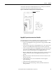
Customer power cables (3-phase input, 3-phase output to protected loads) enter
the top of the Automatic Bypass Switchboard enclosure at the location labeled
CUSTOMER CONNECTION ENTRANCE in Figure 1
. The top panel
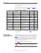
should be removed to punch conduit holes. Bus bar locations and hole pattern are
shown in Figure 4
.
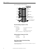
Utility Input and Load Wiring
Connect incoming earth ground conductor to the GROUND bus bar in
accordance with the National Electrical Code and local codes.
UTILITY INPUT cables are terminated at bus bars labeled (left to right)
• L1
• L2
• L3
The Neutral input cables are terminated at the bus bar labeled
• NEUTRAL (For 4-wire systems only: Neutral connection is
required for proper operation)
OUTPUT FOR PROTECTED LOADS cables are terminated
at bus bars labeled
• X1
• X2
• X3
The Neutral output cables, if needed, are terminated at the same bus bar
labeled
• NEUTRAL (present only in 4-wire systems)
Put Automatic Bypass Switchboard circuit breakers in these positions
before energizing the system:
• CBI = OFF (open)
• CBB = ON (closed)
• CBO = OFF (open)
Replace all insulating panels, covers, close and lock all doors
before energizing the system.