User Manual Bulletin 1608M MegaDySC Dynamic Voltage Sag Corrector 1608M—800-2400 Amp Models
Important User Information Solid-state equipment has operational characteristics differing from those of electromechanical equipment. Safety Guidelines for the Application, Installation and Maintenance of Solid State Controls (publication SGI-1.1 available from your local Rockwell Automation sales office or online at http://www.rockwellautomation.com/literature/) describes some important differences between solid-state equipment and hard-wired electromechanical devices.
Table of Contents Ch 1 - Introduction Ch 2 - Installation Ch 3 - Communications Ch 4 - Applying Power Ch 5 - Operation Ch 6 - Display Screen Important User Information. . . . . . . . . . . . . . . . . . . . . . . . . . . . . . . . . . . . . . . . . . . . . . 2 Additional Resources. . . . . . . . . . . . . . . . . . . . . . . . . . . . . . . . . . . . . . . . . . . . . . . . . . . . . 2 Safety Considerations . . . . . . . . . . . . . . . . . . . . . . . . . . . . . . . . . . . . . . . . . . . . . . . .
Table of Contents Ch 7 - Maintenance Ch 8 - Specifications 4 System Event Log . . . . . . . . . . . . . . . . . . . . . . . . . . . . . . . . . . . . . . . . . . . . . . . . . . . 31 System Event Detail . . . . . . . . . . . . . . . . . . . . . . . . . . . . . . . . . . . . . . . . . . . . . . . . 32 System Event Notification . . . . . . . . . . . . . . . . . . . . . . . . . . . . . . . . . . . . . . . . . . . 32 Maintaining the Touch Screen Panel . . . . . . . . . . . . . . . . . . . . . . . . . . . .
Chapter 1 Introduction The Allen-Bradley Bulletin 1608M MegaDySC Dynamic Sag Corrector is engineered to provide years of trouble-free voltage sag (dip) protection. The patented DySC technology does not use batteries, requires only routine maintenance, includes three-stage transient voltage surge suppression, and has unparalleled energy efficiency. Most electronic devices found in industry today are susceptible to power disturbances.
Chapter 1 ATTENTION: Internal components can be easily damaged by electrostatic discharge (ESD). Do not touch circuit boards or electronic components with hands or metal objects. The MegaDySC is not rated to directly power life support equipment. • Ensure the area around the MegaDySC is clean and uncluttered. • Observe all DANGER, CAUTION, and WARNING notices affixed to the inside and outside of the equipment.
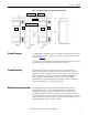
Chapter 2 Installation System Components MegaDySC systems comprise several sections, including multiple "DySC 400A Module” MegaDySC electronics cabinets and one Automatic Bypass Switchboard. The separate shipping split components must be mechanically and electrically interconnected at the time of installation. The MegaDySC cabinets house the static bypass (semiconductor switches) and voltage sag correction electronics.
Chapter 2 Installation System Orientation and Layout The required layout places the MegaDySC enclosures on the right-hand (RH) and left-hand (LH) sides of the Automatic Bypass Switchboard when viewed from the front. Each MegaDySC enclosure is labeled with its required position in the lineup. System components are labeled as in Table 2.
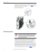
Installation Chapter 2 Figure 2 - Typical System Layout, Front View (800A ER model shown) Comm. Ports Access TB1 Access Bypass Switchboard ER ER LH1 RH1 The MegaDySC and ER cabinet doors are hinged on the left, and clearance must be given to allow the door to swing open 90 degrees to the front of the enclosure, as shown in Figure 1. System Clearance Clearance for the Automatic Bypass switchboard should allow the door to swing (left side hinged) open 90 degrees to the front of its enclosure.
Chapter 2 Installation In addition, the top-mounted wireway sections must be bolted together using the provided 1/4” hardware (torque to 66 lb-in [7.5 N-m]). See Figure 3 for typical fastening locations and hardware arrangement Figure 3 - Mechanical Interconnections. Electrical Interconnections WARNING: Equipment must be earth-grounded according to local and national electric codes. Failure to supply proper equipment grounding may result in electrical shock or death.
Installation Chapter 2 connected to the bus bar terminals labeled L1, L2, L3 and the protected load is connected to the bus bar terminals labeled X1, X2, X3. Figure 4 - Bus Bar Details for Utility Input and Load Output Terminations Top Entry Area NEUTRAL UTILITY INPUT OUTPUT to loads Detail: Typical bus bar hole pattern Right-side cut-away view of Switchboard MegaDySC System Interconnections Checklist The following list of checks is provided for reference only.
Chapter 2 Installation Electrical Terminations for Input and Output Power Customer power cables (3-phase input, 3-phase output to protected loads) enter the top of the Automatic Bypass Switchboard enclosure at the location labeled CUSTOMER CONNECTION ENTRANCE in Figure 1. The top panel should be removed to punch conduit holes. Bus bar locations and hole pattern are shown in Figure 4.
Chapter 3 Communications i-Sense Voltage Monitor An i-Sense voltage monitor is mounted on the Automatic Bypass Switchboard to continuously monitor the 3-phase input and output voltages of the MegaDySC system. The i-Sense is wired in parallel with the bypass circuit breaker CBB. For 3-wire systems, the i-Sense monitors Line-Line voltages. For 4-wire systems, it monitors Line-Neutral voltages. The i-Sense requires communication via the Internet to access the recorded voltage data.
Chapter 3 Communications Figure 6 - Schematic Diagram—Customer Contacts (TB1) CUSTOMER SIDE 1 K1-NC 2 K1-NO 3 4 K2-NC ALM-C ALM-NO OK-NC 5 K2-NO OK-C 6 7 K3-NC 8 K3-NO 9 10 CBB-NC 11 CBB-NO 12 13 120VAC ALM-NC F12 6A 14 K4 15 OK-NO SAG-NC SAG-C SAG-NO CBB-NC CBB-C CBB-NO Not used 120VAC BP Neut BP 1 2 3 4 5 6 7 8 9 10 11 12 } } } } ALARM OUTPUT OK SAG EVENT CBB STATUS (status as shown when CBB is open/OFF) 13 14 15 Customer-provided contact: Close to activate Bypass TB1
Communications Chapter 3 TB1 Contacts Functionality ALARM Contacts The NC contact will be closed during normal operating conditions. The NC contact will open if an alarm condition occurs that inhibits sag correction. It will also close when the DySC system is powered down (when the touchscreen display is off ). If and when an alarm condition clears (for example, a Static Switch Overload no longer exists) the relay will revert to its pre-fault position.
Chapter 3 Communications Conditions that will automatically close the Bypass Circuit Breaker (CBB) are the last five rows of Table 3 on page 20. Remote Seamless BYPASS Command Operation A normally-open PLC contact, relay contact, or push-button contact may be connected between TB1/14 and TB1/15. Close the contact to initiate an automatic seamless bypass operation: CBB will close, then CBI and CBO will open, removing power from the MegaDySC cabinets; voltage sag correction will then be disabled.
Chapter 4 Applying Power ATTENTION: The MegaDySC system must be commissioned by factory-trained engineers. Do not energize the MegaDySC until instructed to do so by commissioning engineers. • After installation make certain there are no metal filings or any conductive debris in or on any components inside the cabinets. • Verify MegaDySC system voltage rating matches ac source voltage. • Ensure all input and output terminations including grounding have been completed and are properly tightened.
Chapter 4 Applying Power Notes: 18 Rockwell Automation Publication 1608M-UM002A-EN-P - September 2013
Chapter 5 Operation System Description Raw utility power enters and routes through the Automatic Bypass switchboard to the load. In maintenance bypass mode the power bypasses the MegaDySC cabinets and passes directly to the load. In this mode the load is unprotected from voltage sags. In the Normal operation mode the MegaDySC cabinets are energized and the power is directed through the MegaDySC, protecting the load. See the following sections for MegaDySC and Automatic Bypass operation details.
Chapter 5 Operation whenever the MegaDySC system is in the Maintenance Bypass mode (CBB closed and CBI open). A list of conditions and indications is given in Table 3. Refer to Chapter 6 for further information on system alarms and status display. Table 3 - Operational Conditions and Indications CONDITION DEFINITION Touchscreen Display STATUS text* INVERTER OPERATION BYPASS MODE Normal: 88.5% < V LINE < 110% Green “OK” Standby Static BP Sag Event: V LINE < 88.5% for less than available runtime.
Operation Chapter 5 ATTENTION: Follow these instructions to avoid interrupting load power! Do not attempt to change the position of any circuit breakers without becoming familiar with the operation of the MegaDySC system. Contact the factory immediately if the system fails to operate as outlined below. Voltage sag protection is not available whenever CBB is closed (red BYPASS CLOSED lamp is lighted).
Chapter 5 Operation Figure 7 - Schematic Diagram of Automatic Bypass Switchboard Power Circuit TVSS Output to load Utility Input (Line) CBB L1 X1 L2 X2 L3 X3 N (if 4-wire system) N Earth Ground CBI CBO L1 L2 L3 N X1 X2 X3 To MegaDySC section(s) Note: The 3-wire MegaDySC models have not been evaluated by Underwriter's Laboratories, Inc.® for connection to a corner-grounded or ungrounded delta power source. Contact Technical Support for assistance.
Operation Chapter 5 Normal Mode The NORMAL mode for the MegaDySC is Input Breaker (CBI) and Output Breaker (CBO) closed. The bypass breaker (CBB) must be open or the MegaDySC will not be able to correct voltage sags. There is a red indicator light on the bypass enclosure that is lighted when the bypass is closed. The green “OK” status box should be shown on the touchscreen display. The green “OK” box indicates that the voltage at the output of the MegaDySC is within the +10%, 13% normal window.
Chapter 5 Operation IMPORTANT In the event of the operation of any over current protection function, check the touchscreen display on the MegaDySC for error codes that may indicate the type of over current condition. ATTENTION: Circuit Breaker settings must not be changed without consulting Technical Support. Circuit Breaker Configuration See the separate Circuit Breaker User Manuals for instructions on how to adjust the breaker set points.
Chapter 6 Display Screen Overview The MegaDySC touch screen display is a window to voltage sags and DySC protection. The display provides system status, voltage sag notification and history, runtime statistics and system history in a simple and intuitive touchbased user interface. Quick Start At commissioning time perform the following steps to configure your system. Note: The touch screen is optimized for use with a plastic stylus or bare finger.
Chapter 6 Display Screen Step 4:Press the “Save” button to store the new date/time and format settings. Note: Pressing “View Model Information” on the “Configuration” screen provides model information about the MegaDySC system. It includes model number, serial number, voltage and current ratings. Unit details are also present including component serial numbers and firmware version numbers. ATTENTION: TO AVOID DAMAGING THE TOUCH DISPLAY: Do not subject the touch display to heavy impact.
Display Screen Chapter 6 The “System Status” screen displays the real-time overall system status (See Table 5). You can access this screen by pressing the “System Status” button in the menu. System Status Figure 10 - System Status Screen n o p Table 5 - System Status Item Description Function System Status Overall system status including: status, availability to correct sags, and internal cabinet temperature.
Chapter 6 Display Screen Cabinet Status When a cabinet image is pressed, detailed status for the selected cabinet will be displayed in a popup window (SeeFigure 11). Press the “Close” button to close the popup and return to the System Status screen. Figure 11 - Cabinet Status Voltage Sags A voltage sag is defined as the period when input rms voltage drops to less than 88.5% of the rated MegaDySC voltage.
Display Screen Chapter 6 The left side of the screen contains the list of voltage sags, which are identified by the following fields: Description Function # Unique ID within the list identifying each voltage sag. Time Start date and time of the voltage sag. RMS% Worst-case RMS voltage (percent of nominal) across all phases. Duration. Duration of the voltage sag. Use the up/down arrows to navigate through the list.
Chapter 6 Display Screen Voltage Sag RMS Voltage Charts The line and load RMS voltage are displayed for each phase (See Figure 14). You can access this screen by pressing the “Charts” button as shown in Figure 13. By pressing the A, B, or C buttons to the right of the charts, you can show or hide each of the three phase voltages.
Display Screen System Events Chapter 6 The MegaDySC tracks all operational alarms. These “System Events” are classified into five groups based on severity, as listed in the following table. Severity Description Informational Purely informational. No action is required. Auto-Resetting The DySC will reset within 60 seconds. No user action is required. User Attention User action may be required to correct a problem. The DySC will reset 60 seconds after the error condition is corrected.
Chapter 6 Display Screen System Event Detail The right side of the System Event Detail page displays detailed information that was recorded during the selected event (See Figure 16). The “Animate” button displays a time-lapse view of the system events as they were recorded. Description Function Time/Duration Event Date: Date and start time of the system event. Duration: The amount of time the event lasted. Type Event ID: Unique ID within the list (0-39) to identify the event.
Display Screen Chapter 6 After the alarm condition is corrected, the MegaDySC must reset before sag correction is available. During this time the display will show “Resetting” in the status field and indicate the amount of time left before the reset is complete. (See Figure 19). When the reset time is complete a new popup window will be displayed. Tap “View Event” to view the complete event detail, or “Close” to close the popup window (See Figure 20).
Chapter 6 Display Screen Restarting the Touch Screen Interface If the touch screen interface becomes unresponsive, it can be reset by one of the following methods: Soft Reset: Press and hold the bottom-right corner of the screen for 5 seconds to reinitialize the touch screen interface. While you are holding this corner, you will see “gui restart” and a timer counting down in the status bar. Hard Reset: Press the blue pushbutton to the left of the touch screen to force the touch panel hardware to reboot.
Chapter 7 Maintenance Preventative Maintenance The MegaDySC requires very little preventative maintenance. The MegaDySC should be checked periodically for proper air flow and status indicator operation. Monthly Checks • Ensure the touch screen display is working and no active events are displayed. • Check that the Automatic Bypass switchboard is in the MegaDySC Normal mode. • Update system time, if needed, see Figure 8 on page 25. • Clean the display screen if needed. See page33.
Chapter 7 Maintenance Table 6 - System Event Table Event Code 1 Code Name Full Name Severity Area Event Description Event Resolution POWER_ON DySC Power On Informational Unit Power re-applied to the DySC. No action needed. 4 T_FAN_ST Fan Test Start Informational Unit Start acknowledgment of DySC fan test. No action needed. 5 T_IN_ST_1 Inverter Test (.5 cycles) Start Informational Unit Start acknowledgment of DySC 0.5 cycle inverter test. No action needed.
Chapter 7 Event Code Maintenance Code Name Full Name Severity Area Event Description Event Resolution 31 CONFIG Configuration Alert Call Service Inverter Controller configuration has changed. Call service. 32 CNTRL_MEM Controller Memory Busy Auto-Resetting Inverter Controller is loading new data into Flash memory. No action needed. 33 UNBALANCE Start-Up Test: DC Bus Unbalance Call Service Inverter Positive and negative halves of the DC bus did not charge equally during power up.
Chapter 7 Maintenance Servicing ATTENTION: Service must be performed by qualified personnel only. Refer to the Hardware Service Manual for detailed instructions. Before attempting any servicing that requires opening the MegaDySC doors first put the system into Maintenance Bypass mode as described in the section Automatic Bypass Switchboard Operation on page 20 WARNING: The MegaDySC and optional ER cabinets are interlocked.
Maintenance Chapter 7 Automatic Bypass Switchboard Fuses Refer to the fuse listing label located on the switchboard cover for fuse size and type. Before replacing a switchboard fuse authorized service personnel will require removal of power to the Automatic Bypass switchboard by opening and locking-out the upstream circuit breaker. WARNING: De-energize the Bypass switchboard before removing covers to access fuses.
Chapter 7 Maintenance Table 7 - MegaDySC Fuse Schedule MegaDySC Main Cabinet Fuses Fuse Reference Fuse Location Fuse Rating Manufacturer Part Number F1, F2, F3 Main Cabinet: Main Power Input 800A/500V Mersen A50QS800-4IL F4, F5, F6 Main Cabinet: Cross-Coupling Transformer 200A/600V Mersen AJT200 F10, F11 Main Cabinet: Output Control Transformer 4A/600V Mersen TRS4R F12 Main Cabinet: Input Control Transformer 2A/600V Mersen TRS2R F13 - F24 (SR Models) Main Cabinet: Dynamic Brake 20A/6
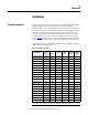
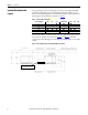
Chapter 8 Specifications Table 8 - Typical Technical Specifications 800-2400 A MegaDySC Electrical Input/Output (Normal Mode—Static Switch) Connection Configuration Series-connected with load. Under normal line condition, the static switch passes utility voltage directly to the load Rated Input Voltage 3-Phase: 380, 400, 415, 460, 480V1 Voltage Range ±10% Static Bypass Current 100% rated rms current continuous, 150%-400% @ 5 sec., 400%-600% @ 0.5 sec., 600% @ 0.
Chapter 8 Specifications Notes: 42 Rockwell Automation Publication 1608M-UM002A-EN-P - September 2013
Rockwell Automation Support Rockwell Automation provides technical information on the Web to assist you in using its products. At http://www.rockwellautomation.com/support, you can find technical manuals, technical and application notes, sample code and links to software service packs, and a MySupport feature that you can customize to make the best use of these tools. You can also visit our Knowledgebase at http://www.rockwellautomation.