User Manual Bulletin 1608M MegaDySC Dynamic Voltage Sag Corrector 1608M—400 Amp Models
Important User Information Solid-state equipment has operational characteristics differing from those of electromechanical equipment. Safety Guidelines for the Application, Installation and Maintenance of Solid State Controls (publication SGI-1.1 available from your local Rockwell Automation sales office or online at http://www.rockwellautomation.com/literature/) describes some important differences between solid-state equipment and hard-wired electromechanical devices.
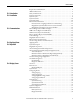
Table of Contents Ch 1 - Introduction Ch 2 - Installation Ch 3 - Communications Ch 4 - Applying Power Ch 5 - Operation Ch 6 - Display Screen Important User Information. . . . . . . . . . . . . . . . . . . . . . . . . . . . . . . . . . . . . . . . . . . . . . 2 Additional Resources. . . . . . . . . . . . . . . . . . . . . . . . . . . . . . . . . . . . . . . . . . . . . . . . . . . . . 2 Safety Considerations . . . . . . . . . . . . . . . . . . . . . . . . . . . . . . . . . . . . . . . . . . . . . . . .
Table of Contents Ch 7 - Maintenance Ch 8 - Specifications 4 Preventative Maintenance . . . . . . . . . . . . . . . . . . . . . . . . . . . . . . . . . . . . . . . . . . . . . . . 39 Monthly Checks . . . . . . . . . . . . . . . . . . . . . . . . . . . . . . . . . . . . . . . . . . . . . . . . . . . . 39 3-6 Month Checks . . . . . . . . . . . . . . . . . . . . . . . . . . . . . . . . . . . . . . . . . . . . . . . . . . 39 Servicing . . . . . . . . . . . . . . . . . . . . . . . . . . . . . . . . . . . . .
Chapter 1 Introduction The Allen-Bradley Bulletin 1608M MegaDySC Dynamic Sag Corrector is engineered to provide years of trouble-free voltage sag (dip) protection. The patented DySC technology does not use batteries, requires only routine maintenance, includes three-stage transient voltage surge suppression, and has unparalleled energy efficiency. Most electronic devices found in industry today are susceptible to power disturbances.
Chapter 1 ATTENTION: Internal components can be easily damaged by electrostatic discharge (ESD). Do not touch circuit boards or electronic components with hands or metal objects. The MegaDySC is not rated to directly power life support equipment. • Ensure the area around the MegaDySC is clean and uncluttered. • Observe all DANGER, CAUTION, and WARNING notices affixed to the inside and outside of the equipment.
Chapter 2 Installation System Components The MegaDySC system consists of two enclosures including one “DySC 400 A Module” MegaDySC section and one Automatic Bypass Switchboard, which are shipped separately and must be mechanically and electrically interconnected at the time of installation. The MegaDySC section houses the static bypass and voltage sag-correction electronics as well as the optional extended-run (ER) module.
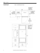
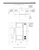
Chapter 2 Installation System Layout 8 Figure 1 - Standard Run (SR) System Layout Rockwell Automation Publication 1608M-UM001A-EN-P - September 2013
Installation Chapter 2 Figure 2 - Extended Run (ER) System Layout Rockwell Automation Publication 1608M-UM001A-EN-P - September 2013 9
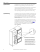
Chapter 2 Installation System Clearance The MegaDySC doors are hinged on the left, and clearance must be given to allow the door to swing open 90 degrees to the front of the enclosure. Clearance for the Automatic Bypass switchboard must allow the front panels to swing (left side hinged) open 90 degrees to the front of its enclosure. Either rear (preferred) or left side access to the Automatic Bypass switchboard will be required during installation wiring and cabinet interconnect wiring.
Installation Chapter 2 Figure 4 - Floor Mounting Detail Electrical Interconnections WARNING: Equipment must be earth-grounded according to local and national electrical codes. Failure to supply proper equipment grounding may result in electrical shock or death. All interconnection wiring will be installed by a factory-trained technician during system commissioning. The MegaDySC cabinet and the Automatic Bypass (ABP) Switchboard are shipped separately. The customer is responsible for system mounting.
Chapter 2 Installation Instructions for energizing loads before commissioning Figure 5 - Rear view of Automatic Bypass Switch board If the MegaDySC system must be installed and put into maintenance bypass mode before commissioning, the installers should put the system enclosures in place as described on page 10, then feed the loose ends of intercabinet cables from the switchboard into the MegaDySC cabinet: 1.
Installation Chapter 2 Figure 6 - Switchboard Terminations and Conduit landing areas Rockwell Automation Publication 1608M-UM001A-EN-P - September 2013 13
Chapter 2 MegaDySC System Installation Connections Checklist • Connect the Automatic Bypass Switchboard ground bus to an earth ground in accordance with the National Electrical Code and local codes. • Connect the AC input (line) conductors to the terminals labeled "L1", "L2" and "L3". The set is labeled "UTILITY INPUT". These terminals are located left of the switchboard. See Figure 6. • Connect the AC output (load) conductors to the terminals labeled "X1", "X2" and "X3".
Chapter 3 Communications Remote Diagnostics and Remote Bypass Relay dry contacts are available for remote monitoring of the state of the Bypass Circuit Breaker CBB and the Input Circuit Breaker CBI shunt-trip condition (See Figure 7). In addition, a customer-supplied relay may be used to remotely command a Seamless Bypass operation, as described in Automatic Bypass Switchboard Operation on page 22.
Chapter 3 Communications CBI Contacts (Input Circuit Breaker) Relay K1 activates on any input circuit breaker shunt-trip signal ("CBI-ST"). Heatsink over-temperature, cabinet over-temperature, SCR Failure, Blown-Fuse or Open-Door indicators will all assert the CBI ST signal to open the input circuit breaker, removing power from the MegaDySC. When this signal is present, Relay K1 is activated and its Normally-Open contacts close.
Communications MegaDySC Status Contacts Chapter 3 Three relay contacts indicate MegaDySC electronics status; refer to Figure 8. The contacts are form A and close upon occurrence of the named event: (a) any SAG EVENT, when rms input voltage drops below 88.5% of rated value; (b) OUTPUT OK, when output voltage remains between 87% and 110%; and (c) a system ALARM event. These relay contact are rated 24V at 1A.
Chapter 3 Communications i-Sense Voltage Monitor Communications The i-Sense voltage monitor is located on the bottom front of the bypass switchboard and is pre-wired to monitor the MegaDySC input and output voltages. The i-Sense Ethernet and Modem communications ports are internally connected to the RJ45 and RJ11 jacks, respectively, located in the upper compartment of the bypass switchboard. See Figure 6 and Figure 9 for conduit entry locations.
Chapter 4 Applying Power ATTENTION: The MegaDySC system must be commissioned by factory-trained engineers. Do not energize the MegaDySC until instructed to do so by commissioning engineers. If the Automatic Bypass switchboard must be installed and energized before commissioning, follow instructions next to Figure 5. • After installation make certain there are no metal filings or any conductive debris in or on any components inside the cabinets.
Chapter 4 Applying Power Notes: 20 Rockwell Automation Publication 1608M-UM001A-EN-P - September 2013
Chapter 5 Operation System Description Raw utility power enters and routes through the Automatic Bypass switchboard to the load. In maintenance bypass mode the power bypasses the MegaDySC cabinet and passes directly to the load. In this mode the load is unprotected from voltage sags. In the Normal operation mode the MegaDySC cabinet is energized and the power is directed through the MegaDySC, protecting the load. See the following sections for MegaDySC and Automatic Bypass operation details.
Chapter 5 Operation whenever the MegaDySC system is in the maintenance bypass mode (CBB closed and CBI open). A list of conditions and indications is given in Table 2. Refer to Chapter 6 for further information on system alarms and status display. Table 2 - Operational Conditions and Indications CONDITION DEFINITION Touchscreen Display STATUS text* INVERTER OPERATION BYPASS MODE Normal: 88.5% < V LINE < 110% Green “OK” Standby Static BP Sag Event: V LINE < 88.5% for less than available runtime.
Operation Chapter 5 ATTENTION: - Follow these instructions to avoid interrupting load power! Contact the factory immediately if the system fails to operate as outlined below. Voltage sag protection is not available whenever CBB is closed (red lamp lighted) Automatic Bypass Switchboard Operating Instructions Automatic System In the event of a fault in the MegaDySC system, bypass (CBB) will close.
Chapter 5 Operation Figure 10 - Schematic Diagram of Automatic Bypass Switchboard Power Circuit TVSS Output to load Utility Input (Line) CBB L1 X1 L2 X2 L3 X3 N (if 4-wire system) N Earth Ground CBI CBO L1 L2 L3 N X1 X2 X3 To MegaDySC section(s) Note: The 3-wire MegaDySC models have not been evaluated by Underwriter's Laboratories, Inc.® for connection to a corner-grounded or ungrounded delta power source. Contact Technical Support for assistance.
Operation Chapter 5 Normal Mode The NORMAL mode for the MegaDySC is Input Breaker (CBI) and Output Breaker (CBO) closed. The bypass breaker (CBB) must be open or the MegaDySC will not be able to correct voltage sags. There is a red indicator light on the bypass enclosure that is lighted when the bypass is closed. The green "OK" status box should be shown on the touchscreen display. The green "OK" box indicates that the voltage at the output of the MegaDySC is within the +10%, 13% normal window.
Chapter 5 Operation protect the inverter module from peak over currents during sag protection operation. IMPORTANT In the event of the operation of any over current protection function, check the touchscreen display on the MegaDySC for error codes that may indicate the type of over current condition. ATTENTION: Circuit Breaker settings must not be changed without consulting Technical Support. Each of CBB, CBI, CBO contains an electronic trip unit with adjustable "Short Delay Pickup.
Chapter 6 Display Screen Overview The MegaDySC® touch screen display is a window to voltage sags and MegaDySC protection. The display provides system status, voltage sag notification and history, runtime statistics and system history in a simple and intuitive touch-based user interface. When the system first starts, a welcome screen displaying the MegaDySC product logo appears. This screen disappears after 5 seconds, when the “Home” screen appears.
Chapter 6 Display Screen Note: To recalibrate from any screen, hold anywhere on the screen for 10 seconds. You will see a small progress bar at the bottom of the screen. When the progress bar reaches 100 percent, the calibration screen will open. Step 3: The “Touch Screen Figure 13 - Touch Screen Calibration Calibration” screen will then appear (See Figure 13). Press and hold on the center of the touch target, release when the touch target begins to flash. Repeat with the next two touch targets.
Display Screen Home Screen Chapter 6 The “HOME” screen of the display provides a snapshot view of the status of the entire system (See Figure 15). You can return to this screen from any other screen by pressing the “HOME” button. After 5 minutes of inactivity (i.e. not pressing the screen), the touch screen will automatically return to the “HOME” screen. The “HOME” screen is divided into four main areas described inTable 3.
Chapter 6 Display Screen System Status The “System Status” screen displays the real-time overall system status.
Display Screen Voltage Sag Events Chapter 6 A voltage sag is defined as the period when input RMS voltage drops to less than 88.5% of the rated DySC voltage. Details of each voltage sag and corresponding MegaDySC protection are captured and saved to the voltage sag log. Voltage Sag Log The “Voltage Sag Log” screen (See Figure 20) displays a list of the last 61 voltage sags. Reach this screen by pressing “VOLTAGE SAGS” button on the “HOME” screen.
Chapter 6 Display Screen Voltage Sag Detail Voltage Sag Detail” screen (See Figure 21) displays all information related to the selected event. Details for the most recent sag event can also be accessed by pressing anywhere in the Last Voltage Sag area of the HOME screen. The worst-case RMS voltage recorded during the event is displayed in the upper window along with the corresponding voltage percentage and the event duration. Table 6 describes the remaining screen content.
Display Screen Voltage Sag RMS Voltage Charts Chapter 6 The line and load RMS voltage (L-N) of each phase is recorded for 8 cycles prior to the start of the voltage sag followed by the first 300 cycles of the voltage sag (See Figure 22). Reach this screen by pressing “CHARTS” on the “Voltage Sag Detail” screen as shown in Figure 21 on page 32. Figure 22 - RMS Voltage Charts Line voltage is shown in red and load voltage is shown in green.
Chapter 6 Display Screen System Events The MegaDySC tracks all operational events which are classified into five groups based on severity. Table 7 - System Event Description Description Function Informational Purely informational. No action is required. Auto-Resetting The MegaDySC will reset within 60 seconds. No user action is required. User Attention User action may be required to correct a problem. The MegaDySC will reset 60 seconds after the error condition is corrected.
Display Screen System Event Detail Chapter 6 The “System Event Detail” screen is displayed when a specific system event is selected by pressing on the “SELECT” button on the “SYSTEM EVENT LOG” screen (See Figure 24 on page 34). It provides detailed information that was recorded during the event (See Figure 25). Figure 25 - System Event Detail Table 9 - System Event Detail Description Time/Duration Function Time: Date and start time of the system event Duration: The amount of time the event lasted.
Chapter 6 Display Screen System Event Notification When the MegaDySC system first detects an event condition, the “System Fault Detection” dialog box will be displayed (See Figure 26). Within the “System Fault Detection” box, the name, severity, and location of the event will be displayed. Figure 26 - System Fault Detection Pressing the “OK” button will open the “System Event Detail” screen. The event will appear in the event list after the event is over.
Display Screen System Configuration Chapter 6 Press the “CONFIG” button at the bottom of the “HOME” screen to enter the “System Configuration” screen (See Figure 28). The “SET SYSTEM CLOCK” and “CALIBRATE TOUCH SENSOR” functions are described at the start of this chapter. Figure 28 - System Configuration Model Information Touch “VIEW MODEL INFORMATION” to go to the “Model Information” screen. (See Figure 29).
Chapter 6 Display Screen Run System Tests Press the “RUN SYSTEM TESTS” to enter the “System Tests” screen. Press “2 MINS” to run the system fans for 2 minutes (See Figure 30). Figure 30 - System Tests Diagnostics Mode This is not a user function. It is numerical code protected for authorized service personnel.
Chapter 7 Maintenance Preventative Maintenance The MegaDySC requires very little preventative maintenance. The MegaDySC should be checked periodically for proper air flow and status indicator operation. Monthly Checks • Ensure the touch screen display is working and no active events are displayed. • Verify that the bypass switch is in the NORMAL mode. • Update system time, if needed, Figure 14 on page 28. • Use a soft cloth to clean the touch display.
Chapter 7 Maintenance Table 11 - System Event Table Event Code Code Name Full Name Severity Area Event Description Event Resolution 1 POWER_ON DySC Power On Informational Unit Power re-applied to the DySC. No action needed. 4 T_FAN_ST Fan Test Start Informational Unit Start acknowledgment of DySC fan test. No action needed. 5 T_IN_ST_1 Inverter Test (.5 cycles) Start Informational Unit No action needed.
Chapter 7 Event Code Maintenance Code Name 34 AC_V_CHK 35 ROLL_CALL 36 COM_VER 37 CNFG_TO 38 CNFG_ERR 39 FIRM_TO 40 FIRM_DIFF 41 SRL_TO 42 SRL_DIFF 44 Full Name Area Call Service Inverter Call Service Unit Call Service Unit Call Service Unit Call Service Unit Call Service Unit Call Service Unit Call Service Unit Start-Up Test: Serial Number Mismatch Informational Unit T_INV_TO Inverter Test Timeout Call Service Unit 46 DOOR_OPEN DySC Cabinet Door Open Manua
Chapter 7 Maintenance Servicing ATTENTION: Service must be performed by qualified personnel only. Before attempting any servicing that requires opening the MegaDySC doors first put the system into Maintenance Bypass mode as described in the section Automatic Bypass Switchboard Operation on page 22 WARNING: The MegaDySC and optional ER cabinets are interlocked.
Maintenance Chapter 7 Automatic Bypass Switchboard Fuses Refer to the fuse listing label located on the switchboard cover for fuse size and type. Before replacing a switchboard fuse authorized service personnel will require removal of power to the Automatic Bypass switchboard by opening and locking-out the upstream circuit breaker. WARNING: De-energize the Bypass switchboard before removing covers to access fuses.
Chapter 7 Maintenance Table 12 - MegaDySC Fuse Schedule MegaDySC Main Cabinet Fuses Fuse Reference Fuse Location Fuse Rating Manufacturer Part Number Factory Part Number F1, F2, F3 Main Cabinet: Main Power Input 800A/500V Mersen A50QS800-4IL 43-00042 F4, F5, F6 Main Cabinet: Cross-Coupling Transformer 200A/600V Mersen AJT200 43-00017 F10, F11 Main Cabinet: Output Control Transformer 4A/600V Mersen TRS4R 43-00110 F12 Main Cabinet: Input Control Transformer 2A/600V Mersen TRS2R 43-00
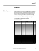
Chapter 8 Specifications Table 13 - Technical Specifications 400 A MegaDySC Electrical Input/Output (Normal Mode—Static Switch) Connection Configuration Series-connected with load. Under normal line condition, the static switch passes utility voltage directly to the load Standard Input Voltage DySC 3-Phase: 380, 400, 415, 460, 480V1 Voltage Range ±10% Static Bypass Current 400A-rms continuous, 150%-400% @ 5 sec., 400%-600% @ 0.5 sec., 600% @ 0.
Chapter 8 Specifications Table 14 - MegaDySC Heat Loading and Typical Efficiency Rated Voltage SR/ER Heat Loss (W) Heat Loss (Btu/h) Efficiency 480V SR 2421 8270 > 99% 480V ER 2852 9740 > 99% 380V SR 2321 7925 > 99% 380V ER 2624 8960 > 99% Table 15 - MegaDySC System Weight 46 3-wire / 4wire SR / ER MegaDySC / MegaDySC+ER weight Automatic Bypass Switchboard Weight Total System Weight 3W SR 1792 lb [813 kg] 1075 lb [488 kg] 2867 lb [1300kg] 3W ER 2656 lb [1205 kg] 107
Rockwell Automation Support Rockwell Automation provides technical information on the Web to assist you in using its products. At http://www.rockwellautomation.com/support, you can find technical manuals, technical and application notes, sample code and links to software service packs, and a MySupport feature that you can customize to make the best use of these tools. You can also visit our Knowledgebase at http://www.rockwellautomation.