
User Manual, 208 Volt, One Second Extended Runt User Manual


8 Rockwell Automation Publication 1608M-UM004A-EN-P - April 2014
Chapter 2 Installation
System Layout
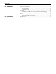
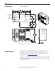
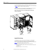
Figure 1 - System layout
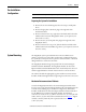
System Clearance
The two Automatic Bypass Switchboard doors are hinged on the left, the
MegaDySC module door is hinged on the left, and the ER Module door is
hinged on the right. Clearance must be given to allow the doors to swing fully
open as shown in the System layout
on page 8.
Only front access and top access are required for installation and commissioning.
Rear access and left side access should be maintained when possible, to simplify
future maintenance tasks.
$8720$7,&
%<3$66
6:,7&+%2$5'
0(*$'\6&
02'8/(
(502'8/(
6+,33,1*63/,7 6+,33,1*63/,7
&86720(5
,23/$7(
72321/<
&$%/((175<
3/$7(
72321/<
6+,33,1*63/,7 6+,33,1*63/,7