User Manual Bulletin 1608M MegaDySC Dynamic Voltage Sag Corrector 1608M— 208 Volt, One Second Extended Runtime Models
Important User Information Solid-state equipment has operational characteristics differing from those of electromechanical equipment. Safety Guidelines for the Application, Installation and Maintenance of Solid State Controls (publication SGI-1.1 available from your local Rockwell Automation sales office or online at http://www.rockwellautomation.com/literature/) describes some important differences between solid-state equipment and hard-wired electromechanical devices.
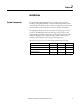
Table of Contents Ch 1 - Introduction Ch 2 - Installation Ch 3 - Communications Ch 4 - Applying Power Ch 5 - Operation Ch 6 - Display Screen Important User Information. . . . . . . . . . . . . . . . . . . . . . . . . . . . . . . . . . . . . . . . . . . . . . 2 Additional Resources. . . . . . . . . . . . . . . . . . . . . . . . . . . . . . . . . . . . . . . . . . . . . . . . . . . . . 2 Safety Considerations . . . . . . . . . . . . . . . . . . . . . . . . . . . . . . . . . . . . . . . . . . . . . . . .
Table of Contents Ch 7 - Maintenance Ch 8 - Specifications 4 Preventative Maintenance . . . . . . . . . . . . . . . . . . . . . . . . . . . . . . . . . . . . . . . . . . . . . . . 41 Monthly Checks . . . . . . . . . . . . . . . . . . . . . . . . . . . . . . . . . . . . . . . . . . . . . . . . . . . . 41 3-6 Month Checks . . . . . . . . . . . . . . . . . . . . . . . . . . . . . . . . . . . . . . . . . . . . . . . . . . 41 Servicing . . . . . . . . . . . . . . . . . . . . . . . . . . . . . . . . . . . . .
Chapter 1 Introduction The Allen-Bradley Bulletin 1608M MegaDySC Dynamic Sag Corrector is engineered to provide years of trouble-free voltage sag (dip) protection. The patented DySC technology does not use batteries, requires only routine maintenance, includes three-stage transient voltage surge suppression, and has unparalleled energy efficiency. Most electronic devices found in industry today are susceptible to power disturbances.
Chapter 1 ATTENTION: Internal components can be easily damaged by electrostatic discharge (ESD). Do not touch circuit boards or electronic components with hands or metal objects. The MegaDySC is not rated to directly power life support equipment. • Ensure the area around the MegaDySC is clean and uncluttered. • Observe all DANGER, CAUTION, and WARNING notices affixed to the inside and outside of the equipment.
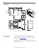
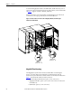
Chapter 2 Installation System Components The Extended Run (ER) MegaDySC system consists of three enclosures including one MegaDySC Module, one Extended Run (ER) Module and one Automatic Bypass Switchboard. The enclosures are shipped separately and must be mechanically and electrically interconnected at the time of installation. The MegaDySC Module houses the static bypass and voltage sag-correction electronics. The ER Module houses the ER energy storage capacitors.
Chapter 2 Installation System Layout Figure 1 - System layout 6+,33,1* 63/,7 6+,33,1* 63/,7 &$%/( (175< 3/$7( 723 21/< &86720(5 , 2 3/$7( 723 21/< $8720$7,& %<3$66 6:,7&+%2$5' 0(*$ '\6& 02'8/( 6+,33,1* 63/,7 System Clearance (5 02'8/( 6+,33,1* 63/,7 The two Automatic Bypass Switchboard doors are hinged on the left, th
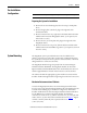
Installation Chapter 2 Pre-Installation Configuration IMPORTANT Perform system configuration steps before mounting and anchoring. Preparing the System for Installation 1. Remove all tan-colored masking dots, blue-colored tape, and all plastic sheets. 2. Remove all eight plastic 13mm hole plugs in the right side of the switchboard cabinet. 3. Remove and save for later step: eight (8) hex-head bolts with lock washer and flat washer in left side of MegaDySC cabinet.
Chapter 2 Installation To attach the MegaDySC module to the ER module, install the four (4) sets of 3/8-16 interconnection bolts along the front of the cabinets, as shown in detail B of Figure 2. Tighten each bolt to 20 N-m [180 in-lb]. Finally, after all interconnection hardware is installed; tighten the anchor bolt connections to the torque specified by the anchor manufacturer.
Installation Chapter 2 Figure 3 - Floor Mounting Detail ; Required Anchor Locations Electrical Interconnections WARNING: Equipment must be earth-grounded according to local and national electric codes.
Chapter 2 Installation Electrical Supply and Load Connections Electrical termination hardware is supplied with each system. One box contains all needed hardware for one system installation. The box is labeled: MegaDySC CUSTOMER CONNECT HARDWARE KIT The incoming 3-phase electrical service and outgoing load cables enter through the top of the switchboard enclosure and connect to the appropriate bus locations. To access the main electrical terminals: 1.
Installation Chapter 2 Figure 5 - Main Power Terminals (front view) Rockwell Automation Publication 1608M-UM004A-EN-P - April 2014 13
Chapter 2 Installation Figure 6 - Automatic Bypass Switchboard Terminations and Conduit Landing Areas &21'8,7 (175< $5($ )25 &86720(5 , 2 3/$7( 5(029( 723 72 '5,// $1' 381&+ &21'8,7 (175< $5($ )25 &$%/( (175< 3/$7( 5(029( 723 72 '5,// $1' 381&+ 6<67(0 *5281'6 1(875$/ :,5( 6<67(06 21/< 287387 72 3527(&7(' /2$'6 87,/,7< ,1387 14 '(7$,/ 9,(: )2
Installation Chapter 2 MegaDySC System Installation Connections Checklist • Connect the Automatic Bypass Switchboard ground bus to an earth ground in accordance with the National Electrical Code and local codes. • Connect the AC input (line) conductors to the terminals labeled “R in”, “S in”, and “T in”. The set is labeled “UTILITY INPUT”. • Connect the AC output (load) conductors to the terminals labeled “R out”, “S out” and “T out”. The set is labeled “PROTECTED LOAD”.
Chapter 2 Installation Notes: 16 Rockwell Automation Publication 1608M-UM004A-EN-P - April 2014
Chapter 3 Communications Communication connections enter through the top of the switchboard enclosure marked CUSTOMER I/O PLATE inFigure 1. This plate can be fitted as needed for conduit entry. Communications terminals are described on the following pages. The ports are located at the top of the left Automatic Bypass Switchboard and are shown in Figure 7. Use RJ45 port number 5 for the communications connection.
Chapter 3 Communications • CBO Closed (CR5A) - Contact is closed when the output circuit breaker (CBO) is closed. Contact is open when CBO is open. • DySC Alarm (CR7A) – Contact is closed when there is an active alarm on the MegaDySC system. Contact is open when there is no alarm on the MegaDySC system. Modbus TCP/IP Communications MegaDySC system status and other items are communicated over a Modbus TCP/IP connection.
Chapter 4 Applying Power ATTENTION: The MegaDySC system must be commissioned by factory-trained engineers. Do not energize the MegaDySC until instructed to do so by commissioning engineers. If the Automatic Bypass switchboard must be installed and energized before commissioning, contact Rockwell Automation technical support. • After installation make certain there are no metal filings or any conductive debris in or on any components inside the cabinets.
Chapter 4 Applying Power Notes: 20 Rockwell Automation Publication 1608M-UM004A-EN-P - April 2014
Chapter 5 Operation System Description Raw utility power enters and routes through the Automatic Bypass switchboard to the load. In maintenance bypass mode the power bypasses the MegaDySC cabinet and passes directly to the load. In this mode the load is unprotected from voltage sags. In the Normal operation mode the MegaDySC cabinet is energized and the power is directed through the MegaDySC, protecting the load. See the following sections for MegaDySC and Automatic Bypass operation details.
Chapter 5 Operation whenever the MegaDySC system is in the maintenance bypass mode (CBB closed and CBI open). A list of conditions and indications is given in Table 1. Refer to Chapter 6 for further information on system alarms and status display. Table 1 - Operational Conditions and Indications CONDITION DEFINITION Touchscreen Display STATUS text* INVERTER OPERATION BYPASS MODE Normal: 88.5% < V LINE < 110% Green “OK” Standby Static BP Sag Event: V LINE < 88.5% for less than available runtime.
Operation Chapter 5 ATTENTION: Follow these instructions to avoid interrupting load power! Contact the factory immediately if the system fails to operate as outlined below. Voltage sag protection is not available whenever CBB is closed (red lamp lighted) Automatic Bypass Switchboard Operating Instructions Automatic System Bypass (CBB) will close in the event of a fault in the MegaDySC system. System will remain in bypass until manually transferred to back to the MegaDySC.
Chapter 5 Operation Figure 9 - Schematic diagram of Automatic Bypass Switchboard Power Circuit Transient Voltage Surge Suppressor (TVSS) Over voltage transient protection is provided on the output of the MegaDySC. Indicator lights for each phase on the front of the TVSS panel (upper left compartment of the Automatic Bypass Switchboard) are illuminated under normal operation. In case of a severe over-voltage transient event, internal fuses in the TVSS module may open.
Operation Chapter 5 Normal Mode The NORMAL mode for the MegaDySC is Input Breaker (CBI) and Output Breaker (CBO) closed. The bypass breaker (CBB) must be open or the MegaDySC will not be able to correct voltage sags. There is a red indicator light on the bypass enclosure that is lighted when the bypass is closed. The green “OK” status box should be shown on the touchscreen display. The green “OK” box indicates that the voltage at the output of the MegaDySC is within the +10%, 13% normal window.
Chapter 5 Operation protect the inverter module from peak over currents during sag protection operation. IMPORTANT In the event of the operation of any over current protection function, check the touchscreen display on the MegaDySC for error codes that may indicate the type of over current condition. ATTENTION: Circuit Breaker settings must not be changed without consulting Technical Support. Each of CBB, CBI, CBO contains an electronic trip unit with adjustable trip settings.
Operation Chapter 5 Open circuit alarm conditions: 1. Open static switch (failure in static switch path) 2. Open main input fuse (F1-F2-F3-F4-F5-F6) 3. Overload of static switch (may cause over-current trip in CBI; see Specifications) 4. Over-temperature of static switch heatsink 5. Over temperature of MegaDySC cabinet ambient air 6. Open cabinet door NOTE: Alarm types 1, 2, and 3 may result in momentary interruption of power to the load before transferring to mechanical bypass.
Chapter 5 Operation Notes: 28 Rockwell Automation Publication 1608M-UM003A-EN-P - April 2014
Chapter 6 Display Screen Overview The MegaDySC® touch screen display is a window to voltage sags and MegaDySC protection. The display provides system status, voltage sag notification and history, runtime statistics and system history in a simple and intuitive touch-based user interface. When the system first starts, a welcome screen displaying the MegaDySC product logo appears. This screen disappears after 5 seconds, when the “Home” screen appears.
Chapter 6 Display Screen Note: To recalibrate from any screen, hold anywhere on the screen for 10 seconds. You will see a small progress bar at the bottom of the screen. When the progress bar reaches 100 percent, the calibration screen will open. Step 3: The “Touch Screen Figure 12 - Touch Screen Calibration Calibration” screen will then appear (See Figure 12). Press and hold on the center of the touch target, release when the touch target begins to flash. Repeat with the next two touch targets.
Display Screen Home Screen Chapter 6 The “HOME” screen of the display provides a snapshot view of the status of the entire system (See Figure 14). You can return to this screen from any other screen by pressing the “HOME” button. After 5 minutes of inactivity (i.e. not pressing the screen), the touch screen will automatically return to the “HOME” screen. The “HOME” screen is divided into four main areas described inTable 2.
Chapter 6 Display Screen System Status The “System Status” screen displays the real-time overall system status.
Display Screen Voltage Sag Events Chapter 6 A voltage sag is defined as the period when input RMS voltage drops to less than 88.5% of the rated DySC voltage. Details of each voltage sag and corresponding MegaDySC protection are captured and saved to the voltage sag log. Voltage Sag Log The “Voltage Sag Log” screen (See Figure 19) displays a list of the last 61 voltage sags. Reach this screen by pressing “VOLTAGE SAGS” button on the “HOME” screen.
Chapter 6 Display Screen Voltage Sag Detail Voltage Sag Detail” screen (See Figure 20) displays all information related to the selected event. Details for the most recent sag event can also be accessed by pressing anywhere in the Last Voltage Sag area of the HOME screen. The worst-case RMS voltage recorded during the event is displayed in the upper window along with the corresponding voltage percentage and the event duration. Table 5 describes the remaining screen content.
Display Screen Voltage Sag RMS Voltage Charts Chapter 6 The line and load RMS voltage (L-N) of each phase is recorded for 8 cycles prior to the start of the voltage sag followed by the first 300 cycles of the voltage sag (See Figure 21). Reach this screen by pressing “CHARTS” on the “Voltage Sag Detail” screen as shown in Figure 20 on page 34. Figure 21 - RMS Voltage Charts Line voltage is shown in red and load voltage is shown in green.
Chapter 6 Display Screen System Events The MegaDySC tracks all operational events which are classified into five groups based on severity. Table 6 - System Event Description Description Function Informational Purely informational. No action is required. Auto-Resetting The MegaDySC will reset within 60 seconds. No user action is required. User Attention User action may be required to correct a problem. The MegaDySC will reset 60 seconds after the error condition is corrected.
Display Screen System Event Detail Chapter 6 The “System Event Detail” screen is displayed when a specific system event is selected by pressing on the “SELECT” button on the “SYSTEM EVENT LOG” screen (See Figure 23 on page 36). It provides detailed information that was recorded during the event (See Figure 24). Figure 24 - System Event Detail Table 8 - System Event Detail Description Time/Duration Function Time: Date and start time of the system event Duration: The amount of time the event lasted.
Chapter 6 Display Screen System Event Notification When the MegaDySC system first detects an event condition, the “System Fault Detection” dialog box will be displayed (See Figure 25). Within the “System Fault Detection” box, the name, severity, and location of the event will be displayed. Figure 25 - System Fault Detection Pressing the “OK” button will open the “System Event Detail” screen. The event will appear in the event list after the event is over.
Display Screen System Configuration Chapter 6 Press the “CONFIG” button at the bottom of the “HOME” screen to enter the “System Configuration” screen (See Figure 27). The “SET SYSTEM CLOCK” and “CALIBRATE TOUCH SENSOR” functions are described at the start of this chapter. Figure 27 - System Configuration Model Information Touch “VIEW MODEL INFORMATION” to go to the “Model Information” screen. (See Figure 28).
Chapter 6 Display Screen Run System Tests Press the “RUN SYSTEM TESTS” to enter the “System Tests” screen. Press “2 MINS” to run the system fans for 2 minutes (See Figure 29). Figure 29 - System Tests Diagnostics Mode This is not a user function. It is numerical code protected for authorized service personnel.
Chapter 7 Maintenance Preventative Maintenance The MegaDySC requires very little preventative maintenance. The MegaDySC should be checked periodically for proper air flow and status indicator operation. Monthly Checks • Ensure the touch screen display is working and no active events are displayed. • Verify that the bypass switch is in the NORMAL mode. • Update system time, if needed, Figure 13 on page 30. • Use a soft cloth to clean the touch display.
Chapter 7 Maintenance Table 10 - System Event Table Event Code Code Name Full Name Severity Area Event Description Event Resolution 1 POWER_ON DySC Power On Informational Unit Power re-applied to the DySC. No action needed. 4 T_FAN_ST Fan Test Start Informational Unit Start acknowledgment of DySC fan test. No action needed. 5 T_IN_ST_1 Inverter Test (.5 cycles) Start Informational Unit No action needed.
Chapter 7 Maintenance Event Code Code Name 33 UNBALANCE Start-Up Test: DC Bus Unbalance Call Service Inverter 34 AC_V_CHK Start-Up Test: AC Voltage Check Call Service Inverter 35 ROLL_CALL Call Service Unit 36 COM_VER Call Service Unit 37 CNFG_TO Call Service Unit 38 CNFG_ERR Call Service Unit 39 FIRM_TO Call Service Unit 40 FIRM_DIFF Call Service Unit 41 SRL_TO Start-Up Test: Controller Roll Call Timeout Start-Up Test: Communication Compatibility Mismatch Start-Up Te
Chapter 7 Maintenance Event Code 44 Code Name Full Name Severity Area 64 ER_CAP_OV ER Capacitor Over-Voltage User Attention Unit 65 ER_FUSE ER Cabinet Fuse Open Call Service Unit 66 ER_UNBAL ER Cabinet DC Bus Unbalance Call Service Unit Event Description The voltage of a capacitor in the ER cabinet exceeded the maximum voltage rating. ER cabinet disconnected. One of the fuses in the ER cabinet was detected open. ER cabinet disconnected.
Maintenance Chapter 7 Servicing ATTENTION: Service must be performed by qualified personnel only. Before attempting any servicing that requires opening the MegaDySC doors first put the system into Maintenance Bypass mode as described in the section Automatic Bypass Switchboard Operation on page 22 WARNING: The MegaDySC cabinet is interlocked.
Chapter 7 Maintenance If the upstream power is interrupted before CBI is opened the fast-discharge circuit will not be triggered. In that case wait at least 30 minutes before opening the MegaDySC cabinet doors to avoid exposure to charged capacitors. High voltage remains on capacitors if the red LED indicators above the module capacitor banks are lighted. Fuses Fast-acting fuses are included to protect the MegaDySC system in the event of a load-short circuit or other conditions.
Maintenance IMPORTANT Chapter 7 A qualified electrician must replace the fuses. Open the front cabinet door(s) to access the fuse holders and fuses. To maintain protection of the MegaDySC, be sure to replace the fuse with the same type and rating. These fuses are available through Rockwell Automation Technical Support. Table 11 - MegaDySC Fuse Schedule Fuse Reference Fuse Location Fuse Rating Manufacturer Manufacturer Part Number Rockwell Automation Cat. No.
Chapter 7 Maintenance Notes: 48 Rockwell Automation Publication 1608M-UM004A-EN-P - April 2014
Chapter 8 Specifications Table 12 - Technical Specifications 800A MegaDySC Electrical Input/Output (Normal Mode—Static Switch) Connection Configuration Series-connected with load. Under normal line condition, the static switch passes utility voltage directly to the load Standard Input Voltage DySC 3-Phase: 208V Voltage Range Frequency ±10% 555 A-rms continuous (200 kVA), 833 A rms continuous (300 kVA) 110%-150% @ 60 sec., 150%-300% @ 5 sec., 300%-400% @ 0.5 sec., 400%-600% @ 0.05 sec.
Chapter 8 Specifications Table 13 - MegaDySC Heat Loading and Typical Efficiency Rated kVA Heat Loss (W) Heat Loss (BTU/h) Efficiency 200 2800 9600 > 98.5% 300 3700 12600 > 98.
Rockwell Automation Support Rockwell Automation provides technical information on the Web to assist you in using its products. At http://www.rockwellautomation.com/support, you can find technical manuals, technical and application notes, sample code and links to software service packs, and a MySupport feature that you can customize to make the best use of these tools. You can also visit our Knowledgebase at http://www.rockwellautomation.