Installation Instructions Bulletin 1608M MegaDySC Dynamic Voltage Sag Corrector 1608M—400 Amp Models
Important User Information Solid-state equipment has operational characteristics differing from those of electromechanical equipment. Safety Guidelines for the Application, Installation and Maintenance of Solid State Controls (publication SGI-1.1 available from your local Rockwell Automation sales office or online at http://www.rockwellautomation.com/literature/) describes some important differences between solid-state equipment and hard-wired electromechanical devices.
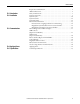
Table of Contents Ch 1 - Introduction Ch 2 - Installation Ch 3 - Communications Ch 4 - Applying Power Ch 5 - Specifications Important User Information. . . . . . . . . . . . . . . . . . . . . . . . . . . . . . . . . . . . . . . . . . . . . . 2 Additional Resources. . . . . . . . . . . . . . . . . . . . . . . . . . . . . . . . . . . . . . . . . . . . . . . . . . . . . 2 Safety Considerations . . . . . . . . . . . . . . . . . . . . . . . . . . . . . . . . . . . . . . . . . . . . . . . . . . . .
Table of Contents Notes: 6 Rockwell Automation Publication 1608M-IN001A-EN-P - September 2013
Chapter 1 Introduction The Allen-Bradley Bulletin 1608M MegaDySC Dynamic Sag Corrector is engineered to provide years of trouble-free voltage sag (dip) protection. The patented DySC technology does not use batteries, requires only routine maintenance, includes three-stage transient voltage surge suppression, and has unparalleled energy efficiency. Most electronic devices found in industry today are susceptible to power disturbances.
Chapter 1 ATTENTION: Internal components can be easily damaged by electrostatic discharge (ESD). Do not touch circuit boards or electronic components with hands or metal objects. The MegaDySC is not rated to directly power life support equipment. • Ensure the area around the MegaDySC is clean and uncluttered. • Observe all DANGER, CAUTION, and WARNING notices affixed to the inside and outside of the equipment.
Chapter 2 Installation System Components The MegaDySC system consists of two enclosures including one “DySC 400 A Module” MegaDySC section and one Automatic Bypass Switchboard, which are shipped separately and must be mechanically and electrically interconnected at the time of installation. The MegaDySC section houses the static bypass and voltage sag-correction electronics as well as the optional extended-run (ER) module.
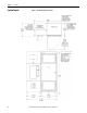
Chapter 2 Installation System Layout 10 Figure 1 - Standard Run (SR) System Layout Rockwell Automation Publication 1608M-IN001A-EN-P - September 2013
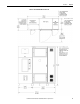
Installation Chapter 2 Figure 2 - Extended Run (ER) System Layout Rockwell Automation Publication 1608M-IN001A-EN-P - September 2013 11
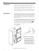
Chapter 2 Installation System Clearance The MegaDySC doors are hinged on the left, and clearance must be given to allow the door to swing open 90 degrees to the front of the enclosure. Clearance for the Automatic Bypass switchboard must allow the front panels to swing (left side hinged) open 90 degrees to the front of its enclosure. Either rear (preferred) or left side access to the Automatic Bypass switchboard will be required during installation wiring and cabinet interconnect wiring.
Installation Chapter 2 Figure 4 - Floor Mounting Detail Electrical Interconnections WARNING: Equipment must be earth-grounded according to local and national electrical codes. Failure to supply proper equipment grounding may result in electrical shock or death. All interconnection wiring will be installed by a factory-trained technician during system commissioning. The MegaDySC cabinet and the Automatic Bypass (ABP) Switchboard are shipped separately. The customer is responsible for system mounting.
Chapter 2 Installation Instructions for energizing loads before commissioning Figure 5 - Rear view of Automatic Bypass Switch board If the MegaDySC system must be installed and put into maintenance bypass mode before commissioning, the installers should put the system enclosures in place as described on page 12, then feed the loose ends of intercabinet cables from the switchboard into the MegaDySC cabinet: 1.
Installation Chapter 2 Figure 6 - Switchboard Terminations and Conduit landing areas Rockwell Automation Publication 1608M-IN001A-EN-P - September 2013 15
Chapter 2 MegaDySC System Installation Connections Checklist • Connect the Automatic Bypass Switchboard ground bus to an earth ground in accordance with the National Electrical Code and local codes. • Connect the AC input (line) conductors to the terminals labeled "L1", "L2" and "L3". The set is labeled "UTILITY INPUT". These terminals are located left of the switchboard. See Figure 6. • Connect the AC output (load) conductors to the terminals labeled "X1", "X2" and "X3".
Chapter 3 Communications Remote Diagnostics and Remote Bypass Relay dry contacts are available for remote monitoring of the state of the Bypass Circuit Breaker CBB and the Input Circuit Breaker CBI shunt-trip condition (See Figure 7). In addition, a customer-supplied relay may be used to remotely command a Seamless Bypass operation, as described in Publication 1608MUM001A-EN-P. These functions are available from terminal block TB1 located in the upper compartment of the bypass switchboard.
Chapter 3 Communications CBI Contacts (Input Circuit Breaker) Relay K1 activates on any input circuit breaker shunt-trip signal ("CBI-ST"). Heatsink over-temperature, cabinet over-temperature, SCR Failure, Blown-Fuse or Open-Door indicators will all assert the CBI ST signal to open the input circuit breaker, removing power from the MegaDySC. When this signal is present, Relay K1 is activated and its Normally-Open contacts close.
Communications MegaDySC Status Contacts Chapter 3 Three relay contacts indicate MegaDySC electronics status; refer to Figure 8. The contacts are form A and close upon occurrence of the named event: (a) any SAG EVENT, when rms input voltage drops below 88.5% of rated value; (b) OUTPUT OK, when output voltage remains between 87% and 110%; and (c) a system ALARM event. These relay contact are rated 24V at 1A.
Chapter 3 Communications i-Sense Voltage Monitor Communications The i-Sense voltage monitor is located on the bottom front of the bypass switchboard and is pre-wired to monitor the MegaDySC input and output voltages. The i-Sense Ethernet and Modem communications ports are internally connected to the RJ45 and RJ11 jacks, respectively, located in the upper compartment of the bypass switchboard. See Figure 6 and Figure 9 for conduit entry locations.
Chapter 4 Applying Power ATTENTION: The MegaDySC system must be commissioned by factory-trained engineers. Do not energize the MegaDySC until instructed to do so by commissioning engineers. If the Automatic Bypass switchboard must be installed and energized before commissioning, follow instructions next to Figure 5. • After installation make certain there are no metal filings or any conductive debris in or on any components inside the cabinets.
Chapter 4 Applying Power Notes: 22 Rockwell Automation Publication 1608M-IN001A-EN-P - September 2013
Chapter 5 Specifications Table 2 - Technical Specifications 400 A MegaDySC Electrical Input/Output (Normal Mode—Static Switch) Connection Configuration Series-connected with load. Under normal line condition, the static switch passes utility voltage directly to the load Standard Input Voltage DySC 3-Phase: 380, 400, 415, 460, 480V1 Voltage Range ±10% Static Bypass Current 400A-rms continuous, 150%-400% @ 5 sec., 400%-600% @ 0.5 sec., 600% @ 0.
Chapter 5 Specifications Table 3 - MegaDySC Heat Loading and Typical Efficiency Rated Voltage SR/ER Heat Loss (W) Heat Loss (Btu/h) Efficiency 480V SR 2421 8270 > 99% 480V ER 2852 9740 > 99% 380V SR 2321 7925 > 99% 380V ER 2624 8960 > 99% Table 4 - MegaDySC System Weight 24 3-wire / 4wire SR / ER MegaDySC / MegaDySC+ER weight Automatic Bypass Switchboard Weight Total System Weight 3W SR 1792 lb [813 kg] 1075 lb [488 kg] 2867 lb [1300kg] 3W ER 2656 lb [1205 kg] 1075
Rockwell Automation Support Rockwell Automation provides technical information on the Web to assist you in using its products. At http://www.rockwellautomation.com/support, you can find technical manuals, technical and application notes, sample code and links to software service packs, and a MySupport feature that you can customize to make the best use of these tools. You can also visit our Knowledgebase at http://www.rockwellautomation.