User Manual Bulletin 1608P HC-DySC Dynamic Voltage Sag Corrector 1608P-200A480V...
Important User Information Solid-state equipment has operational characteristics differing from those of electromechanical equipment. Safety Guidelines for the Application, Installation and Maintenance of Solid State Controls (publication SGI-1.1 available from your local Rockwell Automation sales office or online at http://www.rockwellautomation.com/literature/) describes some important differences between solid-state equipment and hard-wired electromechanical devices.
Table of Contents Ch 1 - Introduction Ch 2 - Installation Ch 3 - Communications Ch 4 - Applying Power and Operation Ch 5 - Display Screen Important User Information. . . . . . . . . . . . . . . . . . . . . . . . . . . . . . . . . . . . . . . . . . . . . . 2 Additional Resources. . . . . . . . . . . . . . . . . . . . . . . . . . . . . . . . . . . . . . . . . . . . . . . . . . . . . 2 Safety Considerations . . . . . . . . . . . . . . . . . . . . . . . . . . . . . . . . . . . . . . . . . . . . . . . . . .
Table of Contents Ch 6 - Maintenance Ch 7 - Specifications and Dimensions 4 Preventative Maintenance . . . . . . . . . . . . . . . . . . . . . . . . . . . . . . . . . . . . . . . . . . . . . . . 31 Monthly Checks . . . . . . . . . . . . . . . . . . . . . . . . . . . . . . . . . . . . . . . . . . . . . . . . . . . . 31 3-6 Month Checks . . . . . . . . . . . . . . . . . . . . . . . . . . . . . . . . . . . . . . . . . . . . . . . . . . 31 Servicing . . . . . . . . . . . . . . . . . . . . . . . . . . . . .
Chapter 1 Introduction The Allen-Bradley Bulletin 1608P HC-DySC Dynamic Sag Corrector is engineered to provide years of trouble-free voltage sag (dip) protection. The patented DySC technology does not use batteries, requires only routine maintenance, includes three-stage transient voltage surge suppression, and has unparalleled energy efficiency. Most electronic devices found in industry today are susceptible to power disturbances.
Chapter 1 ATTENTION: - To reduce the risk of fire or electric shock, install this HC-DySC in a temperature and humidity controlled, indoor environment, free of conductive contaminants. • Avoid installing the HC-DySC directly near heat-emitting equipment such as ovens, heaters, or furnaces. • Ambient temperature must not exceed 40°C (104°F). • Do not operate near water or excessive humidity (95% max).
Chapter 2 Installation Installation Check List Inspecting and Unpacking Before proceeding, please take a few minutes to review the necessary steps to install your HC-DySC. • All packing materials and restraints have been removed. • The HC-DySC is placed in its installed location. • All conduits and cables are properly routed to the HC-DySC. • All power cables are properly terminated. • A ground conductor is properly installed and terminated.
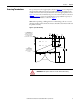
Chapter 2 Installation Floor Mounting The HC-DySC is to be secured to the floor using fasteners and fittings appropriate for the type of floor. Holes are provided in the base channels; see Figure 1 for mounting dimensions. Note: Top or bottom cable entry is allowed. See Figure 1 and Figure 2 on page 9. Figure 1 - Bottom View Floor Mount Dimensions Clearance HC-DySC doors hinge on both right and left. See Figure 30 on page 38 for dimensions including door swing.
Installation Accessing Terminations Chapter 2 For top entry remove the top gland plate, shown in Figure 2, to access input and output terminals. This plate may be removed for drilling or punching holes for conduit. Alternate bottom entry should utilize the bottom gland plate shown in Figure 1. Access to the communications port is above the front doors, as shown in Figure 6 on page 13. A separate conduit knock-out is provided for top entry of communications conductors, as shown in Figure 2.
Chapter 2 Installation 3-Wire vs. 4-Wire Configurations HC-DySC models are available for use with either 3-wire (L1, L2, L3) or 4-wire (L1, L2, L3, N) sources. The input N conductor must be connected to 4-wire models for proper operation. Do not connect a N conductor to 3-wire models. 3- Wire Models Bulletin 1608P part numbers containing V3 are configured for 3-wire source (L1, L2, L3) and 3-wire loads (X1, X2, X3). Do not connect a N conductor to 3-wire models.
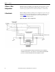
Installation 4- Wire Models Chapter 2 Bulletin 1608P part numbers containing V4 are configured for 4-wire source (L1, L2, L3, N) and either 3-wire or 4-wire loads. The source N conductor must be connected for proper operation of these models. Connect both input and output N conductors to the bus bar labeled NEUTRAL (See Figure 5). Figure 4 shows the 4-wire HC-DySC system wiring schematically, including the internal Bypass Switch. Figure 4 - HC-DySC 4-Wire Configuration.
Chapter 2 Installation Electrical Terminations and Ratings Input terminals (top lugs on CBA) are marked L1, L2, and L3 for the source connections. Output terminal blocks are marked X1, X2, and X3 for the load connections (See Figure 5). In 4-wire models only, connect both input and output N conductors to the NEUTRAL bus bar. Do not connect to the NEUTRAL bus bar in 3-wire models. Replace all shields and covers when wiring is completed. The doors must be closed and latched securely.
Chapter 3 Communications Both dry contacts (relays) that indicate status and a Serial Communications Port (RS-232) are available for monitoring the HC-DySC. Dry Contacts Three relay contacts indicate HC-DySC status. The contacts are form A and close upon occurrence of the named event: (a) any SAG EVENT, when rms input voltage drops below 88.5% of rated value; (b) OUTPUT OK, when output voltage remains between 87% and 110%; and (c) a system ALARM event. The relay contact ratings are 24V at 1A.
Chapter 3 Communications Serial Communications Port The HC-DySC serial port is a DE-9 female connector. The pin-out follows standard RS-232 protocol: pin 2 is RxD, pin 3 is TxD and pin 5 is common (return). All other pins are unused. Contacts are galvanically isolated from the system power and grounds. • Protection: The RS-232 port is ESD-protected to 15kV. • Protocol: 57.6k bps, 8 data bits, one stop bit, no parity, flow control off • Data packets are SLIP encoded (with 2 byte length field).
Chapter 4 Applying Power and Operation Applying Power • Before applying power to the HC-DySC, make certain there are no metal filings or any conductive debris in or on any components inside the cabinet. • Verify HC-DySC voltage rating matches ac source voltage. • Ensure all input/output wiring including grounding has been completed and properly tightened. • Verify CBA circuit breaker is in the ON position before replacing covers. Replace all covers. Close and lock cabinet doors.
Chapter 4 Applying Power and Operation HC-DySC System Operation SHOCK HAZARD: Dangerous voltages are present within the HC-DySC System. The unit should never be operated with the enclosure door open except by qualified and authorized personnel who are trained and familiar with the operation of the unit and the location of components and voltages. Failure to comply with this warning could result in injury or death.
Applying Power and Operation Bypass Switch Modes Chapter 4 The bypass switch has three modes of operation and is configured as shown in Figure 9. Figure 9 - Bypass Switch and Mode Operations. • NORMAL Mode – Input and output contacts are closed. Power flows from the utility source through the DYSC electronics to the load. • TEST Mode – Bypass contacts and input contacts are closed. Power flows directly from the utility to the load through the bypass contacts. DYSC outputs are not connected to the load.
Chapter 4 Applying Power and Operation Operating and Alarm Modes Under some conditions the HC-DySC will trip the internal circuit breaker CBI to prevent damage to the HC-DySC or to protect loads from severe voltage unbalance. Those conditions are the last four listed in the table below. ATTENTION: reclosing of CBI will be inhibited for one (1) minute after CBI has opened for any reason. Attempts to close CBI too early will result in immediate re-tripping.
Chapter 5 Display Screen Overview The HC-DySC® touch screen display is a window to voltage sags and HC-DySC protection. The display provides system status, voltage sag notification and history, runtime statistics and system history in a simple and intuitive touchbased user interface. When the system first starts, a welcome screen displaying the HC-DySC product logo appears. This screen disappears after 5 seconds, when the “Home” screen appears.
Chapter 5 Display Screen Note: To recalibrate from any screen, hold anywhere on the screen for 10 seconds. You will see a small progress bar at the bottom of the screen. When the progress bar reaches 100 percent, the calibration screen will open. Step 3: The “Touch Screen Figure 12 - Touch Screen Calibration Calibration” screen will then appear (See Figure 12). Press and hold on the center of the touch target, release when the touch target begins to flash. Repeat with the next two touch targets.
Display Screen Home Screen Chapter 5 The “HOME” screen of the display provides a snapshot view of the status of the entire system (See Figure 14). You can return to this screen from any other screen by pressing the “HOME” button. After 5 minutes of inactivity (i.e. not pressing the screen), the touch screen will automatically return to the “HOME” screen. The “HOME” screen is divided into four main areas described inTable 3.
Chapter 5 Display Screen System Status The “System Status” screen displays the real-time overall system status.
Display Screen Voltage Sag Events Chapter 5 A voltage sag is defined as the period when input RMS voltage drops to less than 88.5% of the rated DySC voltage. Details of each voltage sag and corresponding HC-DySC protection are captured and saved to the voltage sag log. Voltage Sag Log The “Voltage Sag Log” screen (See Figure 19) displays a list of the last 61 voltage sags. Reach this screen by pressing “VOLTAGE SAGS” button on the “HOME” screen.
Chapter 5 Display Screen Voltage Sag Detail Voltage Sag Detail” screen (See Figure 20) displays all information related to the selected event. Details for the most recent sag event can also be accessed by pressing anywhere in the Last Voltage Sag area of the HOME screen. The worst-case RMS voltage recorded during the event is displayed in the upper window along with the corresponding voltage percentage and the event duration. Table 6 describes the remaining screen content.
Display Screen Voltage Sag RMS Voltage Charts Chapter 5 The line and load RMS voltage (L-N) of each phase is recorded for 8 cycles prior to the start of the voltage sag followed by the first 300 cycles of the voltage sag (See Figure 21). Reach this screen by pressing “CHARTS” on the “Voltage Sag Detail” screen as shown in Figure 20 on page 24. Figure 21 - RMS Voltage Charts Line voltage is shown in red and load voltage is shown in green.
Chapter 5 Display Screen System Events The HC-DySC tracks all operational events which are classified into five groups based on severity. Table 7 - System Event Description Description Function Informational Purely informational. No action is required. Auto-Resetting The HC-DySC will reset within 60 seconds. No user action is required. User Attention User action may be required to correct a problem. The HC-DySC will reset 60 seconds after the error condition is corrected.
Display Screen System Event Detail Chapter 5 The “System Event Detail” screen is displayed when a specific system event is selected by pressing on the “SELECT” button on the “SYSTEM EVENT LOG” screen (See Figure 23 on page 26). It provides detailed information that was recorded during the event (See Figure 24). Figure 24 - System Event Detail Table 9 - System Event Detail Description Time/Duration Function Time: Date and start time of the system event Duration: The amount of time the event lasted.
Chapter 5 Display Screen System Event Notification When the HC-DySC system first detects an event condition, the “System Fault Detection” dialog box will be displayed (See Figure 25). Within the “System Fault Detection” box, the name, severity, and location of the event will be displayed. Figure 25 - System Fault Detection Pressing the “OK” button will open the “System Event Detail” screen. The event will appear in the event list after the event is over.
Display Screen System Configuration Chapter 5 Press the “CONFIG” button at the bottom of the “HOME” screen to enter the “System Configuration” screen (See Figure 27). The “SET SYSTEM CLOCK” and “CALIBRATE TOUCH SENSOR” functions are described at the start of this chapter. Figure 27 - System Configuration Model Information Touch “VIEW MODEL INFORMATION” to go to the “Model Information” screen. (See Figure 28).
Chapter 5 Display Screen Run System Tests Press the “RUN SYSTEM TESTS” to enter the “System Tests” screen. Press “2 MINS” to run the system fans for 2 minutes (See Figure 29). Figure 29 - System Tests Diagnostics Mode This is not a user function. It is numerical code protected for authorized service personnel.
Chapter 6 Maintenance Preventative Maintenance The HC-DySC requires very little preventative maintenance. The HC-DySC should be checked periodically for proper air flow and status indicator operation. Monthly Checks • Ensure the touch screen display is working and no active events are displayed. • Verify that the bypass switch is in the NORMAL mode. • Update system time, if needed, Figure 13 on page 20. • Use a soft cloth to clean the touch display.
Chapter 6 Maintenance Table 11 - System Event Table Event Code Code Name 1 POWER_ON 4 Severity Area DySC Power On Informational Unit Power re-applied to the DySC. No action needed. T_FAN_ST Fan Test Start Informational Unit Start acknowledgment of DySC fan test. No action needed. 5 T_IN_ST_1 Inverter Test (.5 cycles) Start Informational Unit Start acknowledgment of DySC 0.5 cycle inverter test. No action needed.
Chapter 6 Maintenance Event Code Code Name 36 COM_VER 37 CNFG_TO 38 CNFG_ERR 39 FIRM_TO 40 FIRM_DIFF 41 Severity Area Event Description Call Service Unit Firmware communication compatibility problem detected during start-up test. Call service. Call Service Unit Controller communication problem detected during start-up test. Call service. Call Service Unit Controller firmware configuration problem detected during start-up test. Call service.
Chapter 6 Maintenance Servicing ATTENTION: Service must be performed by qualified personnel only. Before attempting any servicing that requires opening the HC-DySC doors first put the system into Bypass (maintenance) mode as described in Maintenance Bypass Operation on page 16. WARNING: The HC-DySC is interlocked. Opening cabinet doors while the system is in operation will result in loss of power to protected loads, unless the bypass switch is in the BYPASS position.
Maintenance Chapter 6 SHOCK HAZARD: Remove all power supplying the HC-DySC before removing the protective cover to reset the CBA circuit breaker. Replace all covers and doors before reapplying power to the HC-DySC. WARNING: Turn the power to the HC-DySC electronics off by placing the Bypass Switch into BYPASS or opening the branch circuit breaker before replacing any fuse. Failure to comply with this warning can result in injury or death.
Chapter 6 Maintenance Transient Voltage Surge Suppressor (TVSS) The HC-DySC includes an internal TVSS device (or SPD), protecting the output (load). Indicator lights on the TVSS show if surge protection is not active (internally disconnected). Power to the TVSS module may be removed by opening the block of fuses F16-F17-F18 and F20 (present in 4-wire models only).
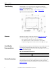
Chapter 7 Specifications and Dimensions Table 13 - Technical Specifications 200 A HC-DySC Electrical Input/Output (Normal Mode—Static Switch) Connection Configuration Series-connected with load. Under normal line condition, the static switch passes utility voltage directly to the load Input Voltage 3-phase: 480V1 Voltage Range ± 10% Available Short Circuit Current 25kA Current Overload (Static Switch) 150% @ 30Sec., 400% @ 5 Sec., 600% @ 0.5 Sec.
Chapter 7 Specifications and Dimensions Table 14 - Heat Dissipation Rating (V) 480V Approximate Dimensions Heat Loss (W) 1664 Heat Loss (Btu/h) 5677 Dimensions are shown in inches (millimeters). Dimensions are not intended to be used for manufacturing purposes. Figure 30 - 200 A HC-DySC Dimensions 0,1,080 > @ &/($5$1&( 72 %( 0$,17$,1(' )520 6,'( $1' %$&.
Rockwell Automation Support Rockwell Automation provides technical information on the Web to assist you in using its products. At http://www.rockwellautomation.com/support, you can find technical manuals, technical and application notes, sample code and links to software service packs, and a MySupport feature that you can customize to make the best use of these tools. You can also visit our Knowledgebase at http://www.rockwellautomation.