
Reference Manual Owner manual

All parameters are specified at 24V, 40A output current, 26°C ambient and after a 5 minutes run-in time, unless noted otherwise.
6 Rockwell Automation Publication 1606-RM010A-EN-P — February 2014
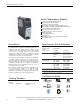
Bulletin 1606 Switched Mode Power Supplies
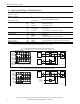
5. Lifetime Expectancy and MTBF
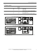
The redundancy module has two input channels which are completely independent from each other. Each control
circuit, auxiliary voltage source, or other circuitry in the module are designed separately for each input. The dual input
redundancy module can be considered as two single redundancy modules combined together in one housing. The only
common point is the circuit trace that ties the two separate circuits together at the output.
The MTBF gures below are for the entire dual input module. If the MTBF number of only one path is needed, simply
double the value from the table.
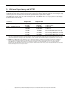
Input / output current
conditions
Input: 2x10A
Output: 20A
Input: 2x20A
Output: 40A
Lifetime expectancy
*)
649 000h
*)
246 000h
*)
at 24V and 40°C
1 835 000h
*)
696 000h
*)
at 24V and 25°C
MTBF
**)
SN 29500, IEC 61709 3 386 000h 2 706 000h at 24V 40°C
5 667 000h 4 686 000h at 24V 25°C
MTBF
**)
MIL HDBK 217F 116 000h 97 000h Ground Fixed GF40 (24V and 40°C)
155 000h 128 000h Ground Fixed GF25 (24V and 25°C)
612 000h 522 000h Ground Benign GB40 (24V and 40°C)
813 000h 687 000h Ground Benign GB25 (24V and 25°C)
*) The Lifetime expectancy shown in the table indicates the minimum operating hours (service life) and is determined by the lifetime
expectancy of the built-in electrolytic capacitors. Lifetime expectancy is specied in operational hours and is calculated according to the
capacitor’s manufacturer specication. The manufacturer of the electrolytic capacitors only guarantees a maximum life of up to 15 years
(131 400h). Any number exceeding this value is a calculated theoretical lifetime which can be used to compare devices.
**) MTBF stands for Mean Time Between Failure, which is calculated according to statistical device failures, and indicates reliability of a
device. It is the statistical representation of the likelihood of a unit to fail and does not necessarily represent the life of a product.
The MTBF gure is a statistical representation of the likelihood of a device to fail. A MTBF gure of e.g. 1 000 000h means that
statistically one unit will fail every 100 hours if 10 000 units are installed in the eld. However, it can not be determined if the failed unit
has been running for 50 000h or only for 100h.