
Reference Manual Owner manual

Reference Manual
egaP egaP
1.
Intended Use .......................................................3
2. Installation Requirements...................................3
3. Input and Output Characteristics .......................4
4. Power Losses........................................................5
5. Lifetime Expectancy and MTBF...........................6
6. Terminals and Wiring..........................................7
7. Functional Diagram.............................................8
8. Front Side and User Elements.............................8
9. EMC......................................................................9
10. Environment ......................................................10
11. Protection Features ...........................................11
12. Safety Features..................................................11
13. Dielectric Strength ............................................11
14.
Certications
.................................................... 12
15. Physical Dimensions and Weight ..................... 13
16. Accessories ........................................................ 14
17. Application Notes............................................. 15
17.1. Recommendations for Redundancy.........15
17.2. Inductive and Capacitive Loads................15
17.3. Lateral Installation Clearances ............15
17.4. 1+1 Redundancy up to 20A......................16
17.5. N+1 Redundancy, Example with 60A ......16
17.6. Mounting Orientations ............................17
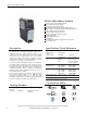
Bulletin 1606 Switched Mode Power Supplies
Catalog Number: 1606-XLSRED40
Index
• PE and symbol—PE is the abbreviation for Protective Earth and has the same meaning as the symbol .
• Earth, Ground—This document uses the term “earth” which is the same as the U.S. term “ground”.
• T.b.d.—To be defined, value or description will follow later.
• DC 24V—A figure displayed with the AC or DC before the value represents a nominal voltage with standard tolerances (usually ±15%) included. E.g.: DC
12V describes a 12V battery whether it is full (13.7V) or flat (10V)
• 24Vdc—A figure with the unit (Vdc) at the end is a momentary figure with no additional tolerance included.
• may, shall, should—Three key words indicating, respectively: flexibility of choice with no implied preference, a mandatory requirement, flexibility of
choice
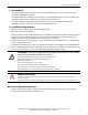
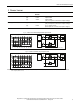
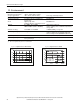
• 1+1 Redundancy—Use of two identical power supplies in parallel to provide
continued operation following most failures in a single power supply. The two
power supply outputs should be isolated from each other by using diodes or
other switching arrangements. E.g. two 10A power supplies are needed to
achieve a 10A redundant system.
• N+1 Redundancy—Use of three or more identical power supplies in parallel
to provide continued operation following most failures in a single power supply.
All power supply outputs should be isolated from each other by using diodes or
other switching arrangements. E.g. to achieve a 40A redundant system, five 10A
power supplies are required in a N+1 redundant system.
Terminology and Abbreviations
N+1
Redundancy
1+1
Redundancy
AC
DC
AC
DC
AC
DC
AC
DC
AC
DC
AC
DC
IN 1
OUT
IN 2 IN 1
OUT
IN 2 IN 1
OUT
IN 2
Load
+
-
AC
DC
AC
DC
Load
+
-
IN 1
OUT
IN 2