
User Manual

All parameters are specified at 24V, 2.5A, 230Vac input, 25ªC ambient and after a 5 minutes run-in time unless noted otherwise.
Rockwell Automation Publication 1606-RM009A-EN-P — February 2014 5
Bulletin 1606 Switched Mode Power Supplies
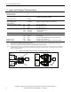
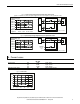
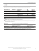
Fig. 3-2 Input to output voltage drop when both inputs draw current
(typical 1+1 redundant case, when the output voltages of the two units are equal or set into “parallel use” mode)
Voltage Drop, typ.
0mV
200mV
400mV
600mV
800mV
1000mV
5A 15A 20A10A
Output:
2x5A2x2.5A
Input:
2x10A2x7.5A
0
0
Input, Output Current
A
.
.
.
2
5
°
C
B
.
.
.
6
0
°
C
A
B
V
A
24V,10A
+
-
24V,10A
+
-
V
A
I
1
I
2
U
1
U
2
I
1
I
2
=
U
2
U
1
= Voltage Drop
U
1
=
U
OUT
-
Output
A
V
I
OUT
U
OUT
Variable
Load,
0-20A
Input 1
Input 2
Output
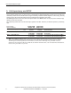
Fig. 3-3 Input to output voltage drop when only one input draws current
Voltage Drop
U
1
=
U
OUT
-
Not used or
power supply
with lower
voltage
V
A
24V,20A
+
-
I
1
U
1
Output
A
V
I
OUT
U
OUT
Variable
Load,
0-20A
Input 1
Input 2
Output
Voltage Drop, typ.
0mV
200mV
400mV
600mV
800mV
1000mV
5A 15A 20
A
10A0
Output Current
A
.
.
.
2
5
°
C
B
.
.
.
6
0
°
C
A
B
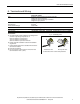
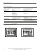
4. Power Losses
DC 24V
Power losses typ.
7.8W input: 2x5A
typ.
8.5W
input: 1x10A
typ.
17.0W
input: 2x10A
Standby power losses typ. 0W at no output current
Fig. 4-1 Power losses
Power Losses, typ.
0
0 5 10 20
4
8
12
16
20
24W
25
A
15
Output Current
1606-XLSRED/XLERED
1606-XLSRED/XLERED