
Reference Manual Instruction Manual

All parameters are specified at 24V, 40A, 230Vac, 25°C ambient and after a 5 minutes run-in time, unless noted otherwise.
12 Rockwell Automation Publication 1606-RM029A-EN-P — April 2014
Bulletin 1606 Switched Mode Power Supplies
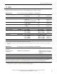
13. Lifetime Expectancy and MTBF
AC 230V
Calculated lifetime expectancy
*)
311 000h
*)
at 24V, 20A and 25°C
110 000h at 24V, 20A and 40°C
169 000h
*)
at 24V, 40A and 25°C
59 000h at 24V, 40A and 40°C
MTBF
**)
SN 29500, IEC 61709 366 000h at 24V, 40A and 40°C
659 000h at 24V, 40A and 25°C
MTBF
**)
MIL HDBK 217F 159 000h at 24V, 40A and 40°C; Ground Benign GB40
215 000h at 24V, 40A and 25°C; Ground Benign GB25
*) The calculated lifetime expectancy shown in the table indicates the minimum operating hours (service life) and is determined by the
lifetime expectancy of the built-in electrolytic capacitors. Lifetime expectancy is specied in operational hours and is calculated according
to the capacitor’s manufacturer specication. The manufacturer of the electrolytic capacitors only guarantees a maximum life of up to 15
years (131 400h). Any number exceeding this value is a calculated theoretical lifetime which can be used to compare devices.
**) MTBF stands for Mean Time Between Failure, which is calculated according to statistical device failures, and indicates reliability of a
device. It is the statistical representation of the likelihood of a unit to fail and does not necessarily represent the life of a product.
The MTBF gure is a statistical representation of the likelihood of a device to fail. A MTBF gure of e.g. 1 000 000h means that
statistically one unit will fail every 100 hours if 10 000 units are installed in the eld. However, it can not be determined if the failed unit
has been running for 50 000h or only for 100h.
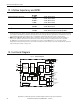
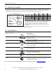
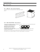
14. Functional Diagram
Fig. 14-1 Functional diagram
+
+
-
-
V
OUT
DC-ok
Contact
Output
Over-
Voltage
Protection
PFC
Converter
Input Fuse
Input Filter
Input Rectier
Inrush Limiter
Output
Voltage
Regulator
Power
Converter
Output
Filter
DC ok
Relay
Output
Voltage
Monitor
Output
Power
Manager
Temper-
ature
Shut-
down
Overload
LED
DC-ok
LED
N
L
Single /
Parallel
Shut-
down
13
14
15
16
Event Datalogger
Shut-down
Input