
Reference Manual


All parameters are specified at 24V, 40A, 3x400Vac, 25°C ambient and after a 5 minutes run-in time, unless noted otherwise.
Rockwell Automation Publication 1606-RM005A-EN-P - February 2014 7
Bulletin 1606 Switched Mode Power Supplies
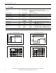
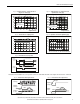
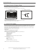
Fig. 6-1 Output voltage vs. output current in
“single use” mode, typ.
Fig. 6-2 Output voltage vs. output current in
“parallel use” mode, typ.
Output Voltage
0
010203040
4
8
12
28V
16
20
24
6050 70A
Output Current
Adjustment Range
A B
A B
A
B
Short-term (4s)
BonusPower
Continuously
available
Output Voltage
(Parallel Use, typ.)
22V
02040
23V
24V
25V
29V
26V
27V
28V
60A503010
Adjustment Range
Output Current
Factory
setting
A
B
A
B
A
B
Short-term (4s)
BonusPower
Continuously
available
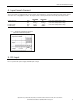
Fig. 6-3 Bonus time vs. output power Fig. 6-4 Dynamic overcurrent capability, typ.
ma
x
.
Bonus Time
0
100 120 130 140 150
170%
1
2
3
4
5s
110 160
Output Power
m
i
n
.
Output Voltage
(dynamic behavior, < 25ms)
0
0
4
8
12
28V
16
20
24
150
A
6030 90 12015 45 75 105 135
Adjustment
Range
Output Current
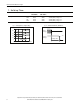
Fig. 6-5 BonusPower recovery time
Power
Demand
100%
t
t
Limitation by
Power Manager
Output
Voltage
Bonus Power disabled
Bonus
Time
Recovery Time
BonusPower is available as soon as power comes on and after the end of an output short circuit or overload.
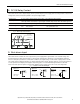
Fig. 6-6 BonusPower after input turn-on Fig. 6-7 BonusPower after output short
100%
Output
Voltage
Input
Voltage
Bonus
Power
Output
Power
150%
Short of
Output
100%
Output
Voltage
Bonus
Power
Output
Power
150%