
User guide

1606-XLS480 3-Phase Power Supply Instruction Manual
1606-XLS480 Bedienungsanleitung für 3-Phasen Stromversorgung
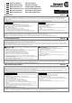
Indicators, LEDs
Overload LED DC-OK LED DC-OK Contact
Normal mode OFF ON Closed
During BonusPower
®
OFF ON Closed
Overload (Vout < 90%) ON OFF Open
Output short circuit ON OFF Open
Temperature Shut-down ON OFF Open
No input power OFF OFF Open
Anzeigelampen
Overload LED DC-OK LED DC-OK Contact
Normalbetrieb AUS EIN geschlossen
Während BonusPower
®
AUS EIN geschlossen
Überlast (Vout < 90%) EIN AUS offen
Ausgangskurzschluss EIN AUS offen
Temperaturabschaltung EIN AUS offen
Keine Eingangsspannung AUS AUS offen
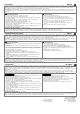
DC-OK Relay Contact (see Fig. 1)
This feature monitors the output voltage, which is produced by the power supply, and is
independent of a return voltage from a unit which is connected in parallel.
Contact closes when the output voltage reaches the adjusted value after turn-on of the power
supply or when the output voltage reaches 90% after a dip of the output.
Contact opens when the output voltage dips more than 10%. Short dips will be extended to a
length of 250ms. Dips shorter than 1ms will be ignored.
Contact ratings: max.: 60Vdc 0.3A, 30Vdc 1A, 30Vac 0.5A, Resistive load, min.: 1mA
Please note:
After turn-on of the power supply, the output voltage has to reach the adjusted level where the
DC-ok relay contact closes and the green DC-ok LED turns on. If this level cannot be achieved,
the red overload LED will stay on. This is an important condition to consider particularly, if the load
is a battery or the power supply is used for N+1 redundant systems.
DC-OK Relais Kontakt (siehe Bild 1)
Diese Funktion überwacht die vom Gerät erzeugte Ausgangsspannung und lässt sich von einer
rückwärts eingespeisten Spannung nicht beeinflussen (z.B.: bei Parallelschaltung)
Kontakt schließt sobald nach dem Einschalten der Ausgang den eingestellten Wert erreicht oder
wenn nach Einbruch des Ausgangs die Spannung wieder >90% des eingestellten Wertes wird.
Kontakt öffnet sobald der Ausgang um mehr als 10% einbricht. Kurze Einbrüche werden auf
250ms verlängert. Einbrüche kürzer 1ms werden ignoriert.
Kontakt Belastbarkeit: max.: 60Vdc 0.3A, 30Vdc 1A, 30Vac 0.5A, (R-Last), min.: 1mA
Zu beachten:
Nach dem Einschalten der Stromversorgung muss die eingestellte Ausgangsspannung erreicht
werden, damit der DC-ok Signalkontakt schließt und die DC-ok LED angeht. Wird dieser Wert
nicht erreicht, leuchtet die Overload LED. Dies kann bei Batterieladeanwendungen oder bei N+1
redundanten Systemen von Bedeutung sein.
Output- and Overload Characteristic
The unit is designed to support loads with a continuous power demand of up to 480W and a short-
term power demand of up to 720W without damage or shut-down.
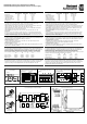
Output characteristic (see Fig. 2)
The curve in this figure is a typical curve for 24V units. The other output voltages have an
equivalent and proportional performance.
BonusPower
®
time (see Fig. 3)
The curve in this figure shows the duration until the output voltage starts dipping when more than
480W is drawn (controlled by software).
Ausgangs- und Überlastverhalten
Die Stromversorgung ist zur Versorgung von Lasten mit einem Dauerleistungsbedarf bis zu 480W
und einem kurzzeitigem Leistungsbedarf bis 720W konstruiert ohne dabei Schaden zu nehmen.
Ausgangskennlinie (siehe Bild 2)
Die Kennlinie in diesem Bild ist die Kennlinie eines typischen 24V Geräts. Die anderen
Ausgangsspannungen zeigen ein proportional vergleichbares Verhalten.
BonusPower
®
Zeit (siehe Bild 3)
Die Kennlinie in diesem Bild gibt die Dauer an bis die Ausgangsspannung sinkt, wenn mehr als
480W entnommen werden (softwaregesteuert).
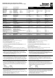
Dielectric Strength (see Fig. 5)
The output voltage is floating and separated from the input according to SELV (IEC/EN 60950-1)
and PELV (EN 60204-1, EN 50178; IEC 62103, IEC 60364-4-41) requirements. Type and factory
tests are conducted by the manufacturer. Field tests may be conducted in the field using the
appropriate test equipment which applies the voltage with a slow ramp (2s up and 2s down).
Connect all phase-terminals together as well as all output poles before the test is conducted.
A B C D
Type Test (60s) 2500Vac 3000Vac 500Vac 500Vac
Factory Test (5s) 2500Vac 2500Vac 500Vac 500Vac
Field Test (5s) 2000Vac 2000Vac 500Vac 500Vac
Isolationsfestigkeit (siehe Bild 5)
Die Ausgangsspannung hat keinen Bezug zur Erde oder Schutzleiter und ist zum Eingang nach
den SELV (IEC/EN 60950-1) und PELV (EN 60204-1, EN 50178, IEC 62103, IEC 60364-4-41)
Standards getrennt. Typ- und Stückprüfungen werden beim Hersteller durchgeführt.
Wiederholungsprüfungen dürfen mittels geeigneten Prüfgenerators mit langsam (2s)
ansteigenden und abfallenden Spannungsrampen in der Anwendung erfolgen. Vor den Tests sind
alle Phasen wie auch alle Ausgangspole miteinander zu verbinden.
A B C D
Typprüfung (60s) 2500Vac 3000Vac 500Vac 500Vac
Stückprüfung (5s) 2500Vac 2500Vac 500Vac 500Vac
Wiederholungsprüfung (5s) 2000Vac 2000Vac 500Vac 500Vac
Operation on Only 2-Phases (see Fig. 4)
No external protection device is required to protect against phase loss failures. The power supply
is allowed to run permanently on two phases, when the de-rating requirements are fulfilled. A
long-term exceeding of the de-rating limits will result in a thermal shut-down of the unit.
Betrieb an nur 2-Phasen (siehe Bild 4)
Es ist kein externer Schutz gegen Ausfall einer Phase erforderlich. Die Stromversorgung darf
dauerhaft an 2 Phasen betrieben werden, wenn die Ausgangsleistung bei höheren Temperaturen
zurückgenommen wird. Eine dauerhafte Überschreitung dieses Grenzwertes kann zu einer
thermischen Abschaltung des Gerätes führen.
Fig. 1 / Bild 1
DC-OK-Signal
Fig. 2 / Bild 2
Output Characteristic /Ausgangskennlinie
Fig. 3 / Bild 3
BonusPower
®
Time / Zeit
Fig. 4 / Bild 4
2-Phase Operation / 2-Phasenbetrieb
Fig. 5 / Bild 5
Insulation / Isolation
250ms
90%
V
ADJ
<
1ms
10%
open
V
OUT
=
V
ADJ
opencl osed cl osed
>
1ms
Output Voltage
0
0 5 10 20 25
4
8
12
28V
16
20
24
35A15 30
Output Current
s
h
o
r
t
-
t
e
r
m
Adjustment
Range
c
o
n
t
i
n
u
o
u
s
m
a
x
.
Bonus Time
0
110 120 130 140 150
160%
Out put Power
1
2
3
4
5s
m
i
n
.
Allowed Output Power
0
-25 0 20
70°
C
25%
50%
75%
100%
125%
150%
c
o
n
t
i
n
u
o
u
s
Ambient Temperature
f
o
r
t
y
p
.
4
s
40 60
A
.
.
.
2
x
4
6
0
t
o
5
5
2
V
a
c
B
.
.
.
2
x
3
4
0
t
o
4
6
0
V
a
c
B
g
A
D
C
B
B
L1
Input DC-ok
Earth
Output
-
+
L3
L2
Fig. 6 / Bild 6
Terminals / Anschlüsse
Fig. 7 / Bild 7
Functional Diagram / Funktionsschaltbild
Fig. 8 / Bild 8
Dimensions / Abmessungen
Insert Wire /
Draht einführen
Snap the lever /
Hebel schließen
+
+
-
-
V
OUT
DC
ok
Output
Over-
Voltage
Protection
PFC
Converter
Input Filter
Input Rectifier
Inrush Limiter
Transient Filter
Output
Voltage
Regulator
Power
Converter
Output
Filter
DC ok
Relay
Output
Voltage
Monitor
Output
Power
Manager
Temper-
ature
Shut-
down
Over-
load
DC
ok
L2
L3
L1
10000044636 (version 00)
PU-347.012.38-10A