
Reference Manual Owner manual

All parameters are specified at an input voltage of 24V, 10A output load, 25°C ambient and after a 5 minutes run-in time unless noted otherwise.
It is assumed that the input power source can deliver a sufficient output current.
Rockwell Automation Publication 1606-RM017A-EN-P — February 2014 9
Bulletin 1606 Switched Mode Power Supplies
9. Buer Time
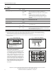
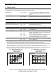
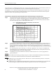
The buer time depends on the capacity and performance of the battery as well as the load current. The diagram
below shows the typical buer times of the 24V output with the standard battery modules at 20°C.
Buer time with battery module 1606-XLSBATASSY1 min. 18’30’’ At 5A output current *)
min. 5’30’’ At 10A output current *)
typ. 20’50’’ At 5A output current, see
Fig. 9-1 **)
typ. 6’30’’ At 10A output current, see Fig. 9-1 **)
Buer time with battery module 1606-XLSBATASSY2 min. 96’30’’ At 5A output current *)
min. 37’50” At 10A output current *)
typ. 126’ At 5A output current, see Fig. 9-1 **)
typ. 53’20” At 10A output current, see Fig. 9-1 **)
*) Minimum value includes 20% aging of the battery and a cable length of 1.5m with a cross section of 2.5mm
2
between the
battery and the DC-UPS and requires a fully charged (min. 24h) battery.
**) Typical value includes 10% aging of the battery and a cable length of 0.3m with a cross section of 2.5mm
2
between the battery
and the DC-UPS and requires a fully charged (min. 24h) battery.
Fig. 9-1 Buer time vs. 24V output current with the battery modules 1606-XLSBATASSY1 and 1606-XLSBATASSY2
Buer Current
515
2
4
6
8
10A
2010 25 30 35 45 5040 55 60 65 70 75 80 85
Buer Time (Minutes)
1606-XLSBATASSY2 typ.
1606-XLSBATASSY1 typ.
.
12
V
7
A
h
b
a
t
t
er
y
1
2
V
2
6
A
h
b
a
t
t
e
r
y
120 150 210 240
300
Min.
180 27090
1606-XLSBATASSY1 typ.
1606-XLSBATASSY2 typ.
90
The buer time is reduced if the 12V output is loaded. This can be calculated according to the following
example:
Example:
24V, 5A and 12V, 4A load
Step1:
Convert the 12V current to a virtual 22.3V level:
Ratio: 12V/22.3V= 0.54 12V, 4A output converted to 22.3V level: 0.54*4A=2.15A
Step 2: Add the computed current to the actual 24V current:
2.15A+ 5A = 7.15A
Step 3: Determine the buer time by using the standard buer time curve
(
)
Fig. 9-1
:
7.15A load with 1606-XLSBATASSY2: Approx. 12 minutes buer time.
The battery capacity is usually specied in amp-hours (Ah) for a 20h discharging event. The battery discharge is non-
linear (due to the battery chemistry). The higher the discharging current, the lower the appropriable battery capacity.
The magnitude of the reduction depends on the discharging cu rrent as well as on the type of battery. High current
battery types can have up to 50% longer buer times co mpared to regular batteries when batteries will be
discharged in less than 1 hour. High discharging currents do not necessarily mean high power losses as the
appropriable battery capacity is reduced with such currents. When the battery begins to recharge after a discharging