
Reference Manual Owner manual

All parameters are specified at an input voltage of 24V, 10A output load, 25°C ambient and after a 5 minutes run-in time unless noted otherwise.
It is assumed that the input power source can deliver a sufficient output current.
6 Rockwell Automation Publication 1606-RM017A-EN-P — February 2014
Bulletin 1606 Switched Mode Power Supplies
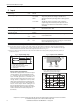
7. Output in Buer Mode
If the input voltage falls below the transfer threshold level, the DC-UPS starts buering without any interruption or
voltage dips. The transfer threshold level is typically 80mV higher than the 24V output voltage in buer mode.
Buering is possible even if the battery is not fully charged.
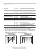
24V Output
Output voltage
nom. DC 24V Output is stabilized and independent from battery voltage.
22.45V ±1%, at no load,
22.25V ±1%, at 10A output current
Ripple and noise voltage max. 20mVpp 20Hz to 20MHz, 50Ohm
Output current nom. 0 - 10A Continuously allowed, 12V output not loaded.
10 - 15A *) 12V output not loaded.
min. 7.0A If 12V output is loaded with 5A.
Short-circuit current min. 17.9A Load impedance 100mOhm **); the 12V output is o during an
overload or short on the 24V.
max. 21A
12V Output
Output voltage
nom. DC 12V Output is stabilized and independent from battery voltage.
Output voltage tolerance
±2%
Ripple and noise voltage typ. 30mVpp 20Hz to 20MHz, 50Ohm ;
nom. 0 - 5A Continuously allowed, may be lower if the 24V output is loaded
more than 7.0A
Output current
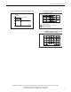
Short-circuit current min. 4A Load impedance 100mOhm, see Fig. 7-5
for typical values.
Continuous constant; the 24V output is on during an overload
or short on the 12V as long as the battery delivers current.
max. 5.5A
*) If the output current is in the range between 10A and 15A (Bonus Power) for longer than 5s, a hardware-controlled
reduction of the maximal output current to 10A occurs. If the 10A are not sucient to maintain the 24V, buering stops at
both outputs after another 5s. Buering is possible again as soon as the input voltage recovers.
**) If the nominal output voltage cannot be maintained in buer mode, the DC-UPS switches o after 5s to save battery
capacity.
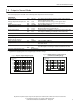
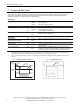
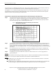
Fig. 7-1 Buering transition, denition
Fig. 7-2 Transfer behavior, typ.
Buer mode
Output
voltage
24V
28V
Input
voltage
t
t
Transfer
threshold
5
0
0
m
s
/
D
I
V
0
V
O
u
t
p
u
t
V
o
l
t
a
g
e
I
n
p
u
t
V
o
l
t
a
g
e
2
4
V
2
2
.
2
5
V
a
t
1
0
A
2
4
V