
Reference Manual Owner manual


All parameters are specified at an input voltage of 24V, 10A output load, 25°C ambient and after a 5 minutes run-in time unless noted otherwise.
It is assumed that the input power source can deliver a sufficient output current.
Rockwell Automation Publication 1606-RM017A-EN-P — February 2014 25
Bulletin 1606 Switched Mode Power Supplies
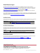
26.3. Using the Inhibit Input
The inhibit input disables buering. In normal mode, a static signal is required. In buer mode, a pulse with a
minimum length of 250ms is required to stop buering. The inhibit is stored and can be reset by cycling the input
voltage.
For service purposes, the inhibit input can also be used to connect a service switch. Therefore, the inhibit signal can
be supplied from the output of the DC-UPS.
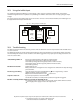
26.4. Troubleshooting
The LEDs on the front of the unit and relay contacts indicate about the actual or elapsed status of the DC-UPS. Please
see also section 14
.
The following guidelines provide instructions for xing the most common failures and problems. Always start with
the most likely and easiest-to-check condition. Some of the suggestions may require special safety precautions. See
notes in section
25 rst.
“Check wiring” LED is on Check correct wiring between the battery and the DC-UPS.
Check battery fuse. Is the batte ry fuse inserted or blown?
Check battery voltage (must be typically between 7.4V and 15.1V).
Check input voltage (must be typically between 22.8V and 30V).
Check battery polarity.
DC-UPS did not buer
Inhibit input was set.
Battery did not have enough time to be charged and is still below the deep discharge
protection limit.
DC-UPS stopped buering Deep discharge protection stopped buering use a larger battery, or allow
sucient time for ch
arging the battery.
Output was overloaded or short circuit reduce load.
Output has shut down
Cycle the input power to reset the DC-UPS.
Let DC-UPS cool down, over temperature protection might have triggered.
DC-UPS constantly switches between normal mode and buer mode
The supplying source on the input is too small and cannot deliver sucient current.
Use a larger power supply or reduce the output load.
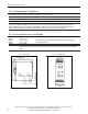
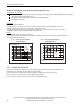
Fig. 26-3 Wiring example for inhibit input
DC-UPS
IN
24V
OUT
24V
Signal Port
BAT
12V
Power
Supply
NL
PE
+ -+ -
Buffered
Load
+
-
+ -+ - + -
Input
Output
+ -
Inhibit
+
-
12V
Battery
Service
Switch