
Reference Manual Owner manual

All parameters are specified at an input voltage of 24V, 10A output load, 25°C ambient and after a 5 minutes run-in time unless noted otherwise.
It is assumed that the input power source can deliver a sufficient output current.
Rockwell Automation Publication 1606-RM017A-EN-P — February 2014 13
Bulletin 1606 Switched Mode Power Supplies
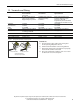
13. Relay Contacts and Inhibit Input
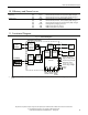
The DC-UPS is equipped with relay contacts and signal inputs for remote monitoring and control of the unit.
Relay contacts:
Ready: Contact is closed when battery is charged more than 85%, no wiring failure is recognized, input
voltage is sucient and inhibit signal is inactive.
Buering: Contact is closed when unit is buering.
Replace Battery: Contact is closed when the unit is powered from the input and the battery quality test (SoH test)
reports a negative result.
Relay contact ratings max 60Vdc 0.3A, 30Vdc 1A, 30Vac 0.5A resistive load
min 1mA at 5Vdc min.
Isolation voltage max 500Vac, signal port to power port
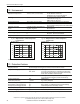
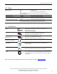
Signal input:
7 +
5,1V
3mA
Inhibit
8 -
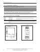
Inhibit: The inhibit input disables buering. In normal mode, a static signal is
required. In buer mode, a pulse with a minimum length of 250ms is
required to stop buering. The inhibit is stored and can be reset by
cycling the input voltage. See also section
26.1 for application hints.
Signal voltage max. 35Vdc
Signal current max. 6mA, current limited
Inhibit threshold min. 6Vdc, buering is disabled above this threshold level
max. 10Vdc
Isolation nom. 500Vac, signal port to power port