
Reference Manual Owner manual

All parameters are specified at an input voltage of 24V, 10A output load, 25°C ambient and after a 5 minutes run-in time unless noted otherwise.
It is assumed that the input power source can deliver a sufficient output current.
Rockwell Automation Publication 1606-RM017A-EN-P — February 2014 11
Bulletin 1606 Switched Mode Power Supplies
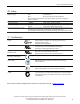
10. Eciency and Power Losses
Eciency typ. 97.5% Normal mode, 24V 10A, 12V 0A, battery fully charged
typ. 96% Normal mode, 24V 7.0A, 12V 5A, battery fully charged
Power losses typ. 3.4W Normal mode, no load, battery fully charged
typ. 6W Normal mode, 24V 10A , 12V 0A, battery fully charged
typ. 10W Normal mode, 24V 12.3A, 12V 5A, battery fully charged
typ. 5.5W During battery charging, no load.
typ. 19W Buer mode, 24V 10A, 12V 0A
typ. 23W Buer mode, 24V 7.0A, 12V 5A
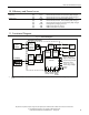
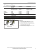
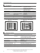
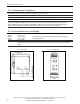
11. Functional Diagram
Fig. 11-1 Functional Diagram
DC-UPS Control Unit
Battery
Charger
Battery
Tester
Cut-off
Relay
Battery
+
-
12V Battery
24V
Power
Supply
Input
-
+
-
+
Reverse
Polarity
Protection
Input Fuse
&
*
Electronic
Current
Limiter
Buffered
Load
+
-
24V Output
Step-up
Converter
Step-down
Converter
+
-
(5) (6)
Ready
Contact
(1) (2)
Buffering
Contact
(3) (4)
Controller
Diagnosis LED (yellow)
Check Wiring LED (red)
Status LED (green)
Buffer-time Limiter
10s, 30s, 1m, 3m, 10m,
End-of-charge Voltage
Inhibit -
Inhibit +
Replace
Battery
Contact
(7)
(8)
12V Output
Buffered
Load
*) Return current protection: this feature uses a Mosfet instead of a diode in order to minimize the voltage drop and power
losses.