
Reference Manual Owner manual

All parameters are specified at an input voltage of 24V, 10A output load, 25°C ambient and after a 5 minutes run-in time unless noted otherwise.
It is assumed that the input power source can deliver a sufficient output current.
10 Rockwell Automation Publication 1606-RM017A-EN-P — February 2014
Bulletin 1606 Switched Mode Power Supplies
event, the process is completed much faster since only the energy which was taken out of the battery needs to be
“relled”. For this reason, the buer time cannot be calculated using the Ah capacity value.
T
he equation “I x t” = capacity in Ah generally leads to incorrect results when the discharging current is higher than
C20 (discharging current for 20h). The battery datasheet needs to be studied and a determination of the expected
buer time can be made by following the example below:
Example how to determine the expected buer time for other battery types and battery sizes:
Step 1 Check the datasheet of the battery which is planned to be used and look for the discharging curve.
Sometimes, the individual discharging curves are marked with relative C-factors instead of current
values. This can easily be converted. Multiply the C-factor by the nominal battery capacity to obtain
the current value. E.g.: 0.6C on a 17Ah battery means 10.2A.
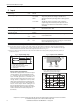
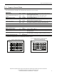
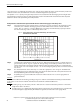
Fig. 9-2 Typical discharging of a typical 17Ah battery, curve taken from
a manufacturer’s datashet
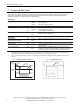
Step 2 Determine the required battery current. Use Fig. 8-1 “Battery discharging current vs. output current” to
get the battery current.
Fig. 8-1 requires the average voltage on the battery terminals. Since there is a
voltage drop between the battery terminals and the battery input of the DC-UPS, it is recommended to
use the curve A or B for output currents > 3A or when using long battery cables. In all other situations,
use curve C.
Step 3 Use the determined current from Step 2 to nd the appropriate curve in Fig. 9-2. The buer time
(Discharging Time) can be found where this curve meets the dotted line. This is the point where the DC-
UPS stops buering due to the under-voltage lockout.
Step 4 Depending on Fig. 9-2, the buer time needs to be reduced to take into account aging eects or
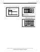
Example:
Buer current is 24V 7.5A and a battery according to Fig. 9-2
is used. The cable between the battery and the DC-UPS
is 1m and has a cross-section of 2.5mm
2
. How much is the maximum achievable buer time?
Answer:
According to Fig. 8-1, the battery current is 18A. Curve A is used since the battery current is > 3A and the
length of the cable is one meter.
According to Fig. 9-2, a buer time (Discharging Time) of 30 minutes can be determined. It is recommended
to reduce this gure to approximately 24 minutes for a guaranteed value and to cover aging eects.
guaranteed values.