
Reference Manual

All parameters are specified at 24V, 10A output load, 25°C ambient and after a 5 minutes run-in time unless noted otherwise.
It is assumed that the input power source can deliver a sufficient output current.
4 Rockwell Automation Publication 1606-RM036A-EN-P — April 2014
Bulletin 1606 Switched Mode Power Supplies
5. Input
Input voltage nom. DC 24V
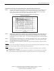
Input voltage ranges nom. 22.5 to 30Vdc Continuous operation, see Fig. 5-1
30 to 35Vdc Temporarily allowed, no damage to the DC-UPS *)
35Vdc Absolute maximum input voltage with no damage to the
DC-UPS
0 to 22.5Vdc The DC-UPS switches into buer mode and delivers
output voltage from the battery if the input was above
the turn-on level before and all other buer conditions
are fullled.
Allowed input voltage ripple
max. 1.5Vpp Bandwidth <400Hz
1Vpp Bandwidth 400Hz to 1kHz
Allowed voltage between input
and earth (ground)
max. 60Vdc or
42.4Vac
Turn-on voltage typ. 22.8Vdc The output does not switch on if the input voltage does
not exceed this level.
max. 23Vdc
Input current **) typ. 120mA Internal current consumption
typ. 1.1A Current consumption for battery charging in constant
current mode at 24V input See
Fig. 8-2 ***)
External capacitors on the input No limitation
*) The DC-UPS shows “Check Wiring” with the red LED and buering is not possible
**) The total input current is the sum of the output current plus the current required to charge the battery during the charging
process and the current which is needed to supply the DC-UPS itself. See also Fig. 5-2. This calculation does not apply
in overload situations where the DC-UPS limits the output current, therefore see
Fig. 5-3
.
***) Please note: This is the input current and not the current owing into the battery in the process of charging. The battery current
is indicated in section 8.
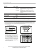
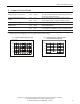
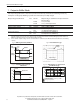
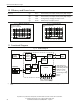
Fig. 5-1 Input voltage range Fig. 5-2 Input current, denitions
A: Rated input voltage range
B: Temp. allowed, no harm to the unit
C: Absolute max. input voltage
D: Buer mode
V
IN
18 30 35V22.50
AB
C
D
V
OUT
Internal
current
consumption
Current
consumption
for battery
charging
Output
Current
Input
Current
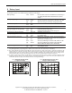
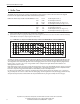
Fig. 5-3 Input current and output voltage vs.
output current, typ. (battery fully charged)
Electronic output current limitation
The DC-UPS is equipped with an electronic output
current limitation. This current limitation works
in a switching mode which reduces the power
losses and heat generation to a minimum. As a
result, the output voltage drops since there is not
enough current to support the load. A positive
eect of the current limit ation in switching mode
is that the input current goes down despite an
increase in the output current resulting in less
stress for the supplying source.
0
0
5
10
15
20A
O
u
t
p
u
t
C
u
r
r
e
n
t
4812 20A
Output Voltage
15
20V
Overload
I
n
p
u
t
C
u
r
r
e
n
t
10