
Reference Manual
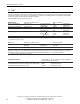

All parameters are specified at 24V, 10A output load, 25°C ambient and after a 5 minutes run-in time unless noted otherwise.
It is assumed that the input power source can deliver a sufficient output current.
20 Rockwell Automation Publication 1606-RM036A-EN-P — April 2014
Bulletin 1606 Switched Mode Power Supplies
24. Installation Notes
Mounting:
The power terminal shall be located on top of the unit. An appropriate electrical and re end-product enclosure
should be considered in the end use application.
Cooling: Convection cooled, no forced air cooling required. Do not obstruct air ow!
Installation clearances: 40mm on top, 20mm on the bottom, 5mm on the left and right side are recommended
when loaded permanently with full power. In case the adjacent device is a heat source, 15mm clearance are
recommended.
Risk of electrical shock, re, personal injury or death!
Turn power o and disconnect battery fuse before working on the DC-UPS. Protect against inadvertent re-powering.
Make sure the wiring is correct by following all local and national codes. Do not open, modify or repair the unit.
Use caution to prevent any foreign objects from entering the housing.
Do not use in wet locations or in areas where moisture and/or condensation are likely to be present.
Service parts:
The unit does not contain any service part. The tripping of an internal fuse is caused by an internal fault. Should damage
or malfunction occur during operation, turn power o immediately and return unit to the factory for inspection!
Wiring and installation instructions:
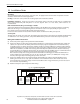
(1) Connect the power supply to the input terminals of the DC-UPS.
(2) Connect the battery to the battery terminals of the DC-UPS. It is recommended to install the battery outside the
cabinet or in a place where the battery will not be heated up by adjacent equipment. Do not install the battery
in airtight housings or cabinets. The battery should be installed according to EN50272-2, which includes sucient
ventilation. Batteries store energy and need to be protected against energy hazards. Use a 30A battery fuse type
ATO® 257 030 (Littelfuse) or similar in the battery path. The battery fuse protects the wires between the battery
and the DC-UPS. It also allows the disconnection of the battery from the DC-UPS which is recommended when
working on the battery or DC-UPS. Disconnect battery fuse before connecting the battery.
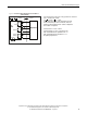
result in malfunction of the DC-UPS. Do not use wires smaller than 2.5mm
2
(or 12AWG) and no longer than
2x1.5m (cord length 1.5m). Avoid voltage drops on this connection.
(3) Connect the buered load to the output terminals of the DC-UPS. The output is decoupled from the input,
allowing load circuits to be easily split into buered and non-buered sections. Non-critical loads can be
connected directly to the power supply and will not be buered. The energy of the battery can then be used in
the circuits that require buering.
(4) Install the battery fuse upon completion of the wiring.
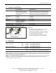
Fig. 24-1 Typical wiring diagram
24V
unbuffered
branch
24V
Power
supply
+
-
NLPE
24V
buffered
branch
Buffered
load
+
-
Unbuffered
load
+
-
DC-UPS
1606-XLS
240-UPS
24V
IN
24V
OUT
12V
BAT
+
-
+
-
+
-
12V
Battery
+
-
Please note: Excessively short or long wires between the DC-UPS and the battery can shorten the buer time or