
Reference Manual

All parameters are specified at 24V, 10A output load, 25°C ambient and after a 5 minutes run-in time unless noted otherwise.
It is assumed that the input power source can deliver a sufficient output current.
Rockwell Automation Publication 1606-RM036A-EN-P — April 2014 15
Bulletin 1606 Switched Mode Power Supplies
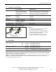
15. Terminals and Wiring
Power terminals
Signal terminals
Type Bi-stable, quick-connect spring-
clamp terminals. IP20 Finger-
touch-proof. Suitable for eld-
and factory installation. Shipped
in open position.
Plug connector with screw terminal. Finger-touch-proof
construction with captive screws for 3.5mm slotted
screwdriver. Suitable for eld and factory installation.
Shipped in open position. To meet GL requirements,
unused terminal compartments should be closed.
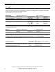
Solid wire 0.5-6mm
2 2
0.2-1.5mm
2 2
Stranded wire 0.5-4mm 0.2-1.5mm
AWG 20-10AWG 22-14AWG
Ferrules Allowed, but not required Allowed, but not required
Pull-out force 10AWG:80N, 12AWG:60N,
14AWG:50N, 16AWG:40N
according to UL486E
Not applicable
Tightening torque Not applicable 0.4Nm, 3.5lb.in
Wire stripping length 10mm / 0.4inch 6mm / 0.24inch
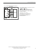
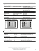
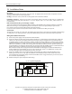
Fig. 15-1 Spring-clamp terminals, connecting a wire
1.
Insert the wire
2.
Close the lever
To disconnect wire:
reverse the procedure
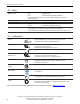
Instructions:
a)
Use appropriate copper cables, that are designed
for an operating temperature of 60°C
b)
Follow national installation codes and regulations.
c)
Ensure that all strands of a stranded wire are fully
inserted in the terminal connection.
d)
Up to two stranded wires with the same cross-
section are permitted in one connection point.
16. Reliability
Lifetime expectancy min. 137 400h At 10A output current, 40°C
min. > 15 years At 5A output current, 40°C
min. > 15 years At 10A output current, 25°C
MTBF SN 29500, IEC 61709 886 000h At 10A output current, 40°C
1 482 000h At 10A output current, 25°C
MTBF MIL HDBK 217F 397 900 At 10A output current , 40°C, ground benign GB40
545 000 At 10A output current , 25°C, ground benign GB25
The Lifetime expectancy shown in the table indicates the operating hours (service life) and is determined by the
lifetime expectancy of the built-in electrolytic capacitors. Lifetime expectancy is specied in operational hours.
Lifetime expectancy is calculated according to the capacitor’s manufacturer specication. The prediction model allows
a calculation of up to 15 years from date of shipment.
MTBF stands for Mean Time Between Failures, which is calculated according to statistical device failures and indicates
reliability of a device. It is the statistical representation of the likelihood of failure of a given unit and does not
necessarily represent the life of a product.