
Reference Manual

All parameters are specified at 24V, 10A output load, 25°C ambient and after a 5 minutes run-in time unless noted otherwise.
It is assumed that the input power source can deliver a sufficient output current.
14 Rockwell Automation Publication 1606-RM036A-EN-P — April 2014
Bulletin 1606 Switched Mode Power Supplies
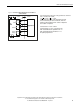
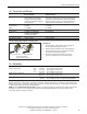
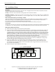
14. Front Side User Elements
A Power Port
Quick-connect spring-clamp terminals, connection for input voltage,
output voltage and battery
B Signal Port
Plug connector with screw terminals, inserted from the bottom.
Connections for the Ready, Buering, Replace Battery relay contacts and
for the Inhibit input. See details in section 13.
.
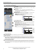
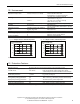
C Green Status LED
Ready: Battery is charged > 85%, no wiring failure is recognized, input
voltage is sucient and in hibit signal is not active.
Charging: Battery is charging and the battery capacity is below 85%.
Buering: Unit is in buer mode.
Flashing pattern of the green status LED:
Ready
Charging
Buffering
ON
OFF
ON
OFF
ON
OFF
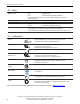
D Yellow Diagnosis LED
Overload: Output has switched o due to long overload in buer mode
or due to high temperatures.
Replace battery: Indicates a battery which failed the battery quality test
(SoH test). Battery should be replaced soon.
Buer-time expired: Output has switched o due to settings of Buer-
timer Limiter. This signal will be displayed for 15 minutes.
Inhibit active: Indicates that buering is disabled due to an active inhibit
signal.
Flashing pattern of the yellow diagnosis LED:
Overload
Replace
Battery
Buffer time
expired
Inhibit
active
ON
OFF
ON
OFF
ON
OFF
ON
OFF
E Red Check Wiring LED
This LED indicates a failure in th e installation (e.g. too low input voltag e), wiring, battery or battery fuse.
F Buer-time Limiter:
User accessible dial which limits the maximum buer time in a buer event to save battery energy. When the
battery begins to recharge after a discharging event, the process is completed musch faster since only the energy
which was taken out of the battery needs to be “relled”. The following times can be selected: 10 seconds, 30
seconds, 1 minute, 3 minutes, 10 minutes or innity (until battery is at) which allows buering until the deep
discharge protection stops buering.
G
End-of-charge Voltage Selector:
The end-of-charge voltage shall be set manually according to the expected temperature in which the battery is
located. The dial on the front of the unit allows a continuous adjustment between +10 and +40°C. 10°C will set
the end-of-charge-voltage to 13.9V, 25°C
13.65V and 40°C 13.4V. If in doubt about the expected temperature,
set the unit to 35°C.
A
B
C
D
E
F
G