Reference Manual Bulletin 1606 Switched Mode Power Supplies Catalog Number: 1606-XLS240-UPS Index 1. 2. 3. 4. 5. 6. 7. 8. 9. 10. 11. 12. 13. 14. 15. 16. Description ...............................................................1 Specification Quick Reference ............................1 Catalog Numbers ...................................................1 Certification Marks ..................................................1 Input ........................................................................
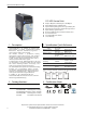
Bulletin 1606 Switched Mode Power Supplies DC-UPS Control Unit ■ ■ ■ ■ ■ ■ ■ ■ ■ 1. Description 2. Specification Quick Reference This uninterruptible power supply (UPS) controller 1606-XLS240-UPS is an addition to standard 24V power supplies to bridge power failures or voltage fluctuations. Expensive downtimes, long restart cycles and loss of data can be avoided.
Bulletin 1606 Switched Mode Power Supplies Intended Use • This device is designed for installation in an enclosure and is intended for the general professional use such as in industrial control, office, communication, and instrumentation equipment. • Do not use this power supply in aircraft, trains, nuclear equipment or similar systems where malfunction may cause severe personal injury or threaten human life. • This device is designed for use in non-hazardous, ordinary or unclassified locations.
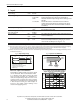
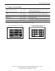
Bulletin 1606 Switched Mode Power Supplies 5. Input Input voltage Input voltage ranges nom. nom. DC 24V 22.5 to 30Vdc 30 to 35Vdc 35Vdc 0 to 22.5Vdc Allowed input voltage ripple max. Allowed voltage between input and earth (ground) Turn-on voltage max. Input current **) typ. 1.5Vpp 1Vpp 60Vdc or 42.4Vac 22.8Vdc max. typ. typ. 23Vdc 120mA 1.1A External capacitors on the input Continuous operation, see Fig.
Bulletin 1606 Switched Mode Power Supplies 6. Output in Normal Mode Output voltage in normal mode nom. DC 24V Voltage drop between input and output max. 0.3V max. max. nom. nom. min. max. 0.45V 20mVpp 15A 360W 17.9A 21A No limitation Ripple and noise voltage Output current Output power Short-circuit current Capacitive and inductive loads The output voltage follows the input voltage reduced by the input to output voltage drop. At 10A output current, see Fig.
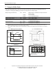
Bulletin 1606 Switched Mode Power Supplies 7. Output in Buffer Mode If the input voltage falls below a certain value (transfer threshold level), the DC-UPS starts buffering without any interruption or voltage dips. Buffering is possible even if the battery is not fully charged. Output voltage in buffer mode nom. Transfer threshold for buffering Ripple and noise voltage Output current typ. max. nom. Short-circuit current min. max.
Bulletin 1606 Switched Mode Power Supplies 8. Battery Input The DC-UPS requires one 12V VRLA battery to buffer the 24V output. Battery voltage nom. Battery voltage range max. typ. min. max. max. Allowed battery sizes Internal battery resistance Battery charging method Battery charging current (CC-mode) nom. max. End-of-charge-voltage (CV-mode) Battery charging time typ. typ. typ. Battery discharging current **) Deep discharge protection ***) DC 12V 9.0 – 15.0V 35Vdc 7.4V 3.
Bulletin 1606 Switched Mode Power Supplies 9. Buffer Time The buffer time depends on the capacity and performance of the battery as well as the load current. The diagram below shows the typical buffer times of the standard battery modules. Buffer time with battery module 1606-XLSBATASSY1 min. min. typ. typ. Buffer time with battery module 1606-XLSBATASSY2 min. min. typ. typ. 19’12’’ 5’42’’ 21’30’’ 6’45’’ 99’30’’ 39’ 130’ 55’ At 5A output current *) At 10A output current *) At 5A output current, see Fig.
Bulletin 1606 Switched Mode Power Supplies Example: How to determine the expected buffer time for other battery types and battery sizes Step 1 Check the datasheet of the battery which is planned to be used and look for the discharging curve. Sometimes, the individual discharging curves are marked with relative C-factors instead of current values. This can easily be converted. The C-factor needs to be multiplied by the nominal battery capacity to get the current value. E.g.: 0.
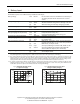
Bulletin 1606 Switched Mode Power Supplies 10. Efficiency and Power Losses Efficiency Power losses typ. typ. typ. typ. typ. 97.8% 2.9W 5.5W 5.0W 18.5W Normal mode, 10A output current, battery fully charged Normal mode, 0A output current, battery fully charged Normal mode, 10A output current, battery fully charged During battery charging, 0A output current Buffer mode, 10A output current Fig. 10-1 Efficiency at 24V, typ. Fig. 10-2 Losses at 24V, typ.
Bulletin 1606 Switched Mode Power Supplies 12. Check Wiring and Battery Quality Tests The DC-UPS is equipped with an automatic “Check Wiring” and “Battery Quality” test. “Check Wiring” test: Under normal circumstances, an incorrect or bad connection from the battery to the DC-UPS or a missing (or blown) battery fuse would not be recognized by the UPS when operating in normal mode. Only when backup is required would the unit be unable to buffer. Therefore, a “Check Wiring” test is included in the DC-UPS.
Bulletin 1606 Switched Mode Power Supplies 13. Relay Contacts and Inhibit Input The DC-UPS is equipped with relay contacts and signal inputs for remote monitoring and control of the input. Relay contacts: Ready: Contact is closed when battery is charged more than 85%, no wiring failure is recognized, input voltage is sufficient and inhibit signal is inactive. Contact is closed when unit is buffering.
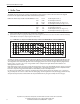
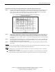
Bulletin 1606 Switched Mode Power Supplies - Input + + Fig. 13-1 Contact control drawing for use in Haz-Loc environments - Output Hazardous Location 1 Non Hazardous Location Ready Isc For Ccable and Lcable, if the capacitance per foot or the inductance per foot is not known, then the following values shall be used: Ccable = 60pF/foot and Lcable = 0.2µH/foot. 2 3 Isc Voc Buffering 4 5 Replace Battery Isc Voc 6 Voc < V max, lsc < lmax, Ca > Ci + Ccable, La > Li + Lcable.
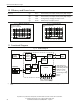
Bulletin 1606 Switched Mode Power Supplies 14. Front Side User Elements A C D E F G B A Power Port Quick-connect spring-clamp terminals, connection for input voltage, output voltage and battery B Signal Port Plug connector with screw terminals, inserted from the bottom. Connections for the Ready, Buffering, Replace Battery relay contacts and for the Inhibit input. See details in section 13. .
Bulletin 1606 Switched Mode Power Supplies 15. Terminals and Wiring Power terminals Bi-stable, quick-connect springclamp terminals. IP20 Fingertouch-proof. Suitable for fieldand factory installation. Shipped in open position. 0.5-6mm2 0.5-4mm2 20-10AWG Allowed, but not required 10AWG:80N, 12AWG:60N, 14AWG:50N, 16AWG:40N according to UL486E Not applicable 10mm / 0.
Bulletin 1606 Switched Mode Power Supplies 17. EMC The unit is suitable for applications in industrial environments as well as in residential, commercial amnd light industry environments without any restrictions. The CE Mark is in conformance with EMC guidelines 89/336/EEC and 93/68/EEC and the low-voltage directive (LVD) 73/23/EEC, 93/68/EEC. A detailed EMC report is available on request.
Bulletin 1606 Switched Mode Power Supplies 18. Environment Operational temperature -25°C to +70°C (-13° to +158°F) Derating 0.43A/°C 0.25A/°C Storage temperature Humidity -40 to +85°C (-40° to +185°F) 5 to 95% r.H. Vibration sinusoidal Shock Altitude Over-voltage category 2-17.8Hz: ±1.6mm; 17.8-500Hz: 2g 30g 6ms, 20g 11ms 0 to 6000m III II 2 Degree of pollution Fig. 18-1 Output current vs. ambient temperature Allowable Output Current in Normal Mode 15A continuous 12.
Bulletin 1606 Switched Mode Power Supplies 20. Safety Output voltage SELV IEC/EN 60950-1 PELV EN 60204-1, EN 50178, IEC 60364-4-41 Max. allowed voltage between any input, output or signal pin and ground: 60Vdc or 42.
Bulletin 1606 Switched Mode Power Supplies 22. Environmental Compliance The unit does not release any silicone and is suitable for the use in paint shops. The unit conforms to the RoHS directive 2002/96/EC. Electrolytic capacitors included in this unit do not use electrolytes such as Quaternary Ammonium Salt Systems. Plastic housings and other molded plastic materials are free of halogens; wires and cables are not PVC insulated.
Bulletin 1606 Switched Mode Power Supplies 24. Installation Notes Mounting: The power terminal shall be located on top of the unit. An appropriate electrical and fire end-product enclosure should be considered in the end use application. Cooling: Convection cooled, no forced air cooling required. Do not obstruct air flow! Installation clearances: 40mm on top, 20mm on the bottom, 5mm on the left and right side are recommended when loaded permanently with full power.
Bulletin 1606 Switched Mode Power Supplies 25. Accessories Battery Modules Two pre-assembled battery modules with a single 12V battery are available for different buffer times. As an option, the mounting brackets are also available without batteries. This option offers more flexibility in selecting an appropriate battery and can result in savings in shipping and logistics. See individual datasheets for each model.
Bulletin 1606 Switched Mode Power Supplies 26. Application Notes 26.1. Battery Replacement Intervals Batteries have a limited life time. They degrade slowly beginning from the production and need to be replaced periodically. The design life figures can be found in the individual datasheets of the batteries and are usually specified specified according to the Eurobat guideline or according to specifications from the manufacturer.
Bulletin 1606 Switched Mode Power Supplies Example for calculating the service life and the required replacement cycle: Parameters for the example: A 7Ah battery with a design life of 3-5 years is used (e.g. Yuasa battery from the 1606-XLSBATASSY1 module) The average ambient temperature is 30°C One buffer event consumes approx. 25% of the achievable buffer time. One buffer event per day Calculation: Ambient temperature influence: According to Fig.
Bulletin 1606 Switched Mode Power Supplies 26.3. Using the Inhibit Input The inhibit input disables buffering. In normal mode, a static signal is required. In buffer mode, a pulse with a minimum length of 250ms is required to stop buffering. The inhibit is stored and can be reset by cycling the input voltage. For service purposes, the inhibit input can also be used to connect a service switch. Therefore, the inhibit signal can be supplied from the output of the DC-UPS. Fig.
Rockwell Automation Support Rockwell Automation provides technical information on the Web to assist you in using its products. At http://www.rockwellautomation.com/support, you can find technical manuals, technical and application notes, sample code and links to software service packs, and a MySupport feature that you can customize to make the best use of these tools. You can also visit our Knowledgebase at http:// www.rockwellautomation.