
Manual
1606-XLS240-UPS DC-UPS Instruction Manual / DC-USV Bedienungsanleitung
*) Do not energize while condensation is present / Nicht betreiben solange das Gerät Kondensation aufweist.
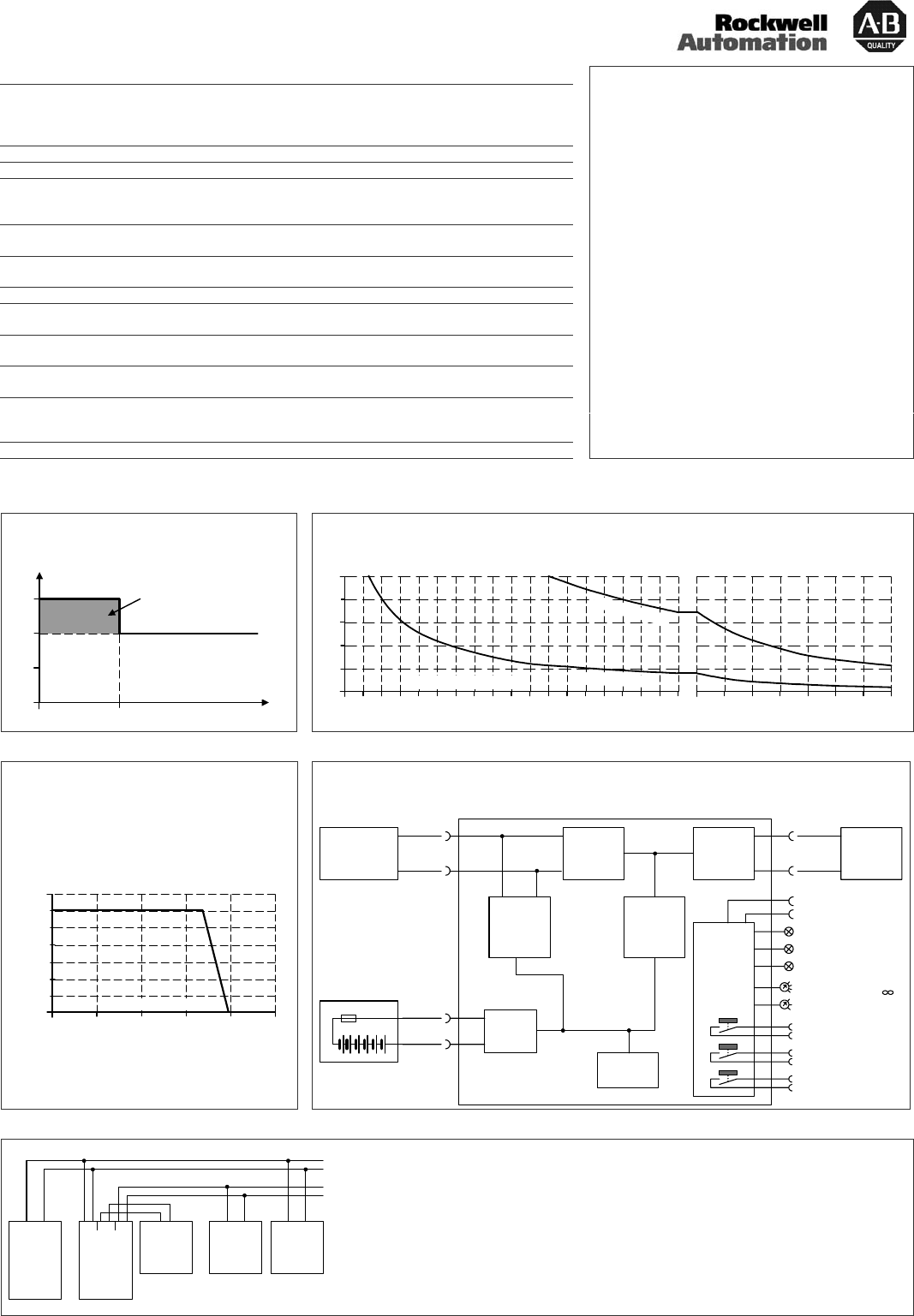
Output current limitation (Buffer mode), typ.
Ausgangsstrombegrenzung (Pufferbetrieb), typ.
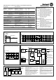
Buffer time vs. output current, typ. / Pufferzeit in Abhängigkeit des Ausgangsstroms, typ.
Output
Current
05 Sec.
15A
10A
Tim e
5A
BonusPower
®
@ 2 2 . 4 V
@ 2 2 . 4 V
Buf f er Curr ent
515
2
4
6
8
10A
2010 25 30 35 45 5040 55 60 65 70 75 80 85
Buffer Time (Minutes)
1
2
V
7
A
h
b
a
t
t
e
r
y
1
2
V
2
6
A
h
b
a
t
t
e
r
y
120 150 210 240
300
Min.
180 2709090
Output current limitation (Normal mode), typ.
Ausgangsstrombegrenzung (Normalbetrieb), typ.
Out put Volt age
0
0 5 10 15 20
4
8
12
28V
16
20
24
25
A
Output Current
Functional diagram / Funktionsschaltbild
-
+
-
+
DC- UPS
24V
Power
Supply
Input /
Output
Isolator
Boost
Converter
Battery
Charger
Electronic
Current
Limiter
Battery
Tester
+
-
Buffered
Load
Safety
Relay
Input Output
Battery
Diagnosis LED (yellow)
Status LED (green)
Inhibit +
Controller
Check Wiring LED (red)
Replace Battery
Buffering Contact
Ready Contact
End-of-Charge Voltage
(7)
Inhibit -
(8)
(1)
(2)
(3)
(4)
(5)
(6)
+
-
12V Battery
Buffer Time Limiter
10s, 30s, 1m, 3m, 10m,
24V
unbuffered
24V
Power
supply
+
-
NLPE
12V
Battery
Module
+
-
Buffered
load
+
-
Unbuffered
load
+
-
24V
buffered
DC-UPS
24V
IN
24V
OUT
12V
BAT
+
-
+
-
+
-
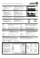
Verdrahtungsanweisung:
Schließen Sie die Stromversorgung and die “Input”
Klemmen der DC-USV an.
Schließen Sie die Batterie an die “Batterie” Klemmen
der DC-USV an.
Benutzen Sie keine kleineren Anschlussdrähte als
2,5mm
2
(oder 12 AWG) und nicht länger als 2x1.5m
(Kabellänge 1.5m). Batterien speichern Energien
und müssen gesichert werden. Verwenden Sie
angemessene Sicherungen für die Batterie!
Schließen Sie die zu puffernde Last an die „Output“
Klemmen der DC-USV an. Unkritische Lasten
können direkt an die Stromversorgung
angeschlossen werden.
Wiring Instructions:
Connect the power supply to the „Input“ terminals of
the DC-UPS.
Connect the battery to the “Battery” terminals of the
DC-UPS.
Use wires not smaller than 2.5mm
2
(or 12 AWG) and
not longer than 2x1.5m (cord length 1.5m). Batteries
store energy and need to be protected against
energy hazards. Use appropriate fuses on the
battery!
Connect the buffered load to the “Output” terminals
of the DC-UPS. Uncritical loads can be connected
directly to the power supply.
Technical Data Technische Daten
Input Voltage Eingangsspannung DC 24V (22.5…30Vdc)
Input Current (Stand-by mode) Eingangsstrom (Ruhemodus) typ 0.12A
Input Current (Charging mode)) Eingangsstrom (Lademodus) max 1.3A
Voltage Drop IN/OUT at 10A Spannungsabfall IN/OUT bei 10A max 0.3V
Transfer Threshold Zuschaltschwelle typ 22.5V
Output Voltage (Buffer mode) Ausgangsspannung (Pufferbetrieb) typ 22.4V
Output Current (Normal mode) Ausgangsstrom (Normalbetrieb) min 15A
(Buffer mode < 5s) (Pufferbetrieb < 5s) min 15A
(Buffer mode > 5s) (Pufferbetrieb > 5s) min 10A
Power Losses at 10A (Normal mode) Verlustleistung bei 10A (Normalbetrieb) typ 5.5W
at 0A (Normal mode) bei 0A (Normalbetrieb) typ 2.9W
Operational Temperature Range Betriebstemperaturbereich nom -25 to 60°C
Non-Operational Temperature Range Transport- und Lagertemperaturbereich nom -40 to 85°C
Humidity, IEC 60068-2-30 *) Feuchte IEC 60068-2-30 *) max 95% r.H.
Vibration, IEC 60068-2-6 Schwingen, IEC 60068-2-6 2g
Shock, IEC 60068-2-27 Schocken, IEC 60068-2-27 30g 6ms, 20g 11ms
Degree of protection, EN 60529 Schutzart, EN 60529 IP20
Degree of pollution, EN 50178 Verschmutzungsgrad, EN 50178 2
Dimension (wxhxd) Abmessungen (BxHxT) 49x124x117mm
Weight Gewicht max 530g, 1.17lb
Allowed Battery Sizes Erlaubte Batteriegrößen 3.9Ah … 27Ah
Recommended Battery Modules 12V, 7Ah
12V, 26Ah
Empfohlene Batterie Module 12V, 7Ah
12V, 26Ah
1606-XLSBAT1
1606-XLSBAT3
Limited Warranty (years) Gewährleistung (Jahre) 1
Terminology and Abbreviations
Normal Mode Describes a condition where the battery is fully
charged, the input voltage is in range and the
output is loaded within the allowed limits.
Buffer Mode Describes a condition where the input voltage is
below the transfer threshold, the unit is buffering
and the output is loaded within the allowed limits.
Charging Mode Describes a condition where the battery is
charging, the input voltage is in range and the
output is loaded within the allowed limits.
Standby Mode Describes a condition where the battery is
fully charged, the input voltage is in range
and the output is not loaded.
Inhibit Disables the buffer mode.
Begriffe und Abkürzungen
Normalbetrieb Batterie voll geladen, Eingangspannung ist im
normalen Bereich und der Ausgang ist mit den
erlaubten Werten belastet.
Pufferbetrieb Die Eingangsspannung liegt unter der
Zuschaltschwell-Spannung, das Gerät puffert und
der Ausgang ist in dem erlaubten Bereich belastet.
Lademodus Batterie wird geladen, Eingangspannung ist im
normalen Bereich und der Ausgang ist mit den
erlaubten Werten belastet.
Ruhemodus Batterie voll geladen, Eingangspannung ist im
normalen Bereich, keine Last am Ausgang.
Inhibit Aktives Signal unterbindet den Pufferbetrieb