
Manual

1606-XLS180, 1606-XLS240 1-Phase Power Supply Instruction Manual
1606-XLS180, 1606-XLS240 Bedienungsanleitung für 1-Phasen Stromversorgung
EMC Electromagnetic Compatibility
These power supplies are suitable for applications in industrial environment as well as in
residential, commercial and light industry environment without any restrictions. These devices
comply with FCC Part 15 rules.
CE mark is in conformance with EMC directive 2004/108/EC as well as the low-voltage directive
(LVD) 2006/95/EC.
EMC Immunity: EN 61000-6-1, EN 61000-6-2
EMC Emission EN 61000-6-3, EN 61000-6-4, FCC Part 15 Class B
EMV Elektromagnetische Verträglichkeit
Diese Stromversorgungen erfüllen die Anforderungen für Anwendungen in industrieller Umgebung
und für den Wohn-, Geschäfts- und Gewerbebereich ohne Einschränkungen. Die Geräte erfüllen
auch die Anforderungen der FCC Teil 15.
Das CE Zeichen ist angebracht und erklärt die Erfüllung der EMV Richtlinie 2004/108/EG wie
auch der Niederspannungsrichtlinie 2006/95/EG.
Störfestigkeit: EN 61000-6-1, EN 61000-6-2
Störaussendung: EN 61000-6-3, EN 61000-6-4, FCC Part 15 Klasse B
Indicators, LEDs
Overload LED DC-OK LED DC-OK Contact
Normal mode OFF ON Closed
During BonusPower
®
OFF ON Closed
Overload (Vout < 90%) ON OFF Open
Output short circuit ON OFF Open
Temperature Shut-down flashing OFF Open
No input power OFF OFF Open
Anzeigelampen
Overload LED DC-OK LED DC-OK Contact
Normalbetrieb AUS EIN geschlossen
Während BonusPower
®
AUS EIN geschlossen
Überlast (Vout < 90%) EIN AUS offen
A
usgangskurzschluss EIN AUS offen
Temperaturabschaltung blinken AUS offen
Keine Eingangsspannung AUS AUS offen
DC-OK Relay Contact (see Fig. 1)
This feature monitors the output voltage, which is produced by the power supply, and is
independent of a return voltage from a unit which is connected in parallel.
Contact closes when the output voltage reaches the adjusted value after turn-on of the power
supply or when the output voltage reaches 90% after a dip in the output.
Contact opens when the output voltage dips more than 10%. Short dips will be extended to a
length of 250ms. Dips shorter than 1ms will be ignored.
Contact ratings: max.: 60Vdc 0.3A, 30Vdc 1A, 30Vac 0.5A, resistive load, min. current 1mA
DC-OK Relais Kontakt (siehe Bild 1)
Diese Funktion überwacht die vom Gerät erzeugte Ausgangsspannung und lässt sich von einer
rückwärts eingespeisten Spannung nicht beeinflussen (z.B.: bei Parallelschaltung)
Kontakt schließt sobald nach dem Einschalten der Ausgang den eingestellten Wert erreicht oder
wenn nach Einbruch des Ausgangs die Spannung wieder >90% des eingestellten Wertes wird.
Kontakt öffnet sobald der Ausgang um mehr als 10% einbricht. Kurze Einbrüche werden auf
250ms verlängert. Einbrüche kürzer 1ms werden ignoriert.
Kontakt Belastbarkeit: max.: 60Vdc 0.3A, 30Vdc 1A, 30Vac 0.5A, (R-Last), min. Strom 1mA
Output- and Overload Characteristic
The unit is designed to support loads with a continuous power demand of up to 240W (1606-
XLS180B: 180W) and a short-term power demand of up to 360W (1606-XLS180B: 270W) without
damage or shut-down.
Output characteristic (see Fig. 2)
The curve in this figure is a typical curve for 24V unit. The other output voltages have an
equivalent and proportional performance.
BonusPower
®
time (see Fig. 3)
The curve in this figure shows the duration until the output voltage starts dipping when more than
240W (1606-XLS180B: 180W) is drawn (controlled by software).
Ausgangs- und Überlastverhalten
Die Stromversorgung ist zur Versorgung von Lasten mit einem Dauerleistungsbedarf bis zu 240W
(1606-XLS180B: 180W) und einem kurzzeitigem Leistungsbedarf bis 360W (1606-XLS180B:
270W) konstruiert ohne dabei Schaden zu nehmen.
Ausgangskennlinie (siehe Bild 2)
Die Kennlinie in diesem Bild ist die Kennlinie eines typischen 24V Gerätes. Die anderen
A
usgangsspannungen zeigen ein proportional vergleichbares Verhalten.
BonusPower
®
Zeit (siehe Bild 3)
Die Kennlinie in diesem Bild gibt die Dauer an bis die Ausgangsspannung sinkt, wenn mehr als
240W (1606-XLS180B: 180W) entnommen werden (softwaregesteuert).
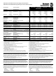
Dielectric Strength (see Fig. 4)
The output voltage is floating and separated from the input according to SELV (IEC/EN 60950-1)
and PELV (EN 60204-1, EN 50178; IEC 62103, IEC 60364-4-41) requirements. Type and factory
tests are conducted by the manufacturer. Field tests may be conducted in the field using the
appropriate test equipment which applies the voltage with a slow ramp (2s up and 2s down).
Connect all phase-terminals together as well as all output poles before the test is conducted.
When testing, set the cut-off current settings to the value in the table below.
A B C D
Type Test (60s) 2500Vac 3000Vac 500Vac 500Vac
Factory Test (5s) 2500Vac 2500Vac 500Vac 500Vac
Field Test (5s) 2000Vac 2000Vac 500Vac 500Vac
Cut-off current setting >10mA >10mA >20mA >1mA
Isolationsfestigkeit (siehe Bild 4)
Die Ausgangsspannung hat keinen Bezug zur Erde oder Schutzleiter und ist zum Eingang nach
den SELV (IEC/EN 60950-1) und PELV (EN 60204-1, EN 50178, IEC 62103, IEC 60364-4-41)
Standards getrennt. Typ- und Stückprüfungen werden beim Hersteller durchgeführt. Wieder-
holungsprüfungen dürfen mittels geeigneten Prüfgenerators mit langsam (2s) ansteigenden und
abfallenden Spannungsrampen in der Anwendung erfolgen. Vor den Tests sind alle Phasen wie
auch alle Ausgangspole miteinander zu verbinden. Während der Tests darf die Strom-
A
bschaltschwelle nicht kleiner als der in der Liste angegebene Wert sein.
A B C D
Typprüfung (60s) 2500Vac 3000Vac 500Vac 500Vac
Stückprüfung (5s) 2500Vac 2500Vac 500Vac 500Vac
Wiederholungsprüfung (5s) 2000Vac 2000Vac 500Vac 500Vac
Strom- Abschaltschwelle >10mA >10mA >20mA >1mA
Fig. 1 / Bild 1
DC-OK-Signal
Fig. 2 / Bild 2
Output Characteristic /Ausgangskennlinie
Fig. 3 / Bild 3
BonusPower
®
Time / Zeit
Fig. 4 / Bild 4
Insulation / Isolation
250ms
90% V
ADJ
<1ms
10%
open
V
OUT
=
V
ADJ
openclosed closed
>1ms
c
o
n
t
i
n
u
o
u
s
Output Voltage
0
0 5 10 15 20
4
8
12
28V
16
20
24
25
A
Output Current
s
h
o
r
t
-
t
e
r
m
Adjustment
Range
Bonus Time
0
110 120 130 140 150
160%
Output Power
1
2
3
7
4
5
6
8
9
10s
m
i
n
m
a
x
typ
A
D
C
B
B
Input DC-ok
Earth
Output
-
+
N
L
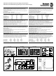
Fig. 5 / Bild 5
Terminals / Anschlüsse
Fig. 6 / Bild 6
Functional Diagram / Funktionsschaltbild
Fig. 7 / Bild 7
Dimensions / Abmessungen
Insert wire / Draht einführen
+
+
-
-
DC-ok
contact
Output
Over-
Voltage
Protection
PFC
Converter
Output
Voltage
Regulator
Power
Converter
Output
Filter
DC-ok
Relay
Output
Voltage
Monitor
Output
Power
Manager
Temper-
ature
Shut-
down
Overload
lamp
DC-ok
lamp
Input Fuse
Input Filter
Input Rectifier
Active Transient Filter &
Inrush Current Limiter
V
OUT
L
N
Snap the lever / Hebel schließen
10000044634 (version 01)
PU-339.013.38-10A