
Reference Manual Instruction Manual

All parameters are specified at 24V, 2.5A, 230Vac input, 25°C ambient and after a 5 minutes run-in time, unless noted otherwise.
6 Rockwell Automation Publication 1606-RM007A-EN-P - February 2014
Bulletin 1606 Switched Mode Power Supplies
5. Output
Output voltage nom. 24V
Adjustment range min. 24-28V guaranteed
max. 30V *) at clockwise end position of potentiometer
Factory setting 24.5V ±0.2%, at full load, cold unit
Line regulation max. 10mV 85-264Vac
Load regulation max. 100mV static value, 0A 2.5A
Ripple and noise voltage max. 50mVpp 20Hz to 20MHz, 50Ohm
Output capacitance typ. 1 600μF
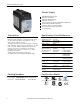
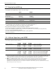
Output current nom. 2.5A at 24V, see Fig. 5-1
nom. 2.1A at 28V, see Fig. 5-1
Output power nom. 60W
Short-circuit current min. 3.6A load impedance 400mOhm, see Fig. 5-1
max. 6.2A load impedance 400mOhm, see Fig. 5-1
*) This is the maximum output voltage which can occur at the clockwise end position of the potentiometer due to tolerances. There is no
guarantee this value will be achieved. The typical value is about 28.6V.
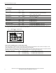
Fig. 5-1 Output voltage vs. output current,
typ.
Output Voltage
0
0
4
8
12
28V
16
20
24
6A54
Adjustment
Range
Output Current
a) 100Vac
b) 120Vac
c) 230Vac
b
c
a
Peak current capability (up to several milliseconds)
The power supply can deliver a peak current which is higher than the specied short term current. This helps to start
current demanding loads or to safely operate subsequent circuit breakers.
The extra current is supplied by the output capacitors inside the power supply. During this event, the capacitors will be
discharged and causes a voltage dip on the output. Detailed curves can be found in section 22-1.
Peak current voltage dips typ. from 24V to 16V at 5A for 50ms, resistive load
typ. from 24V to 15V at 12.5A for 2ms, resistive load
typ. from 24V to 10.5V at 12.5A for 5ms, resistive load
12 3