
Reference Manual Instruction Manual

All parameters are specified at 24V, 2.5A, 230Vac input, 25°C ambient and after a 5 minutes run-in time, unless noted otherwise.
Rockwell Automation Publication 1606-RM007A-EN-P - February 2014 5
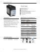
Bulletin 1606 Switched Mode Power Supplies
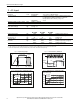
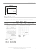
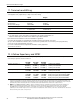
Fig. 3-5 De-rating requirements for
low input voltages
0
85Vac
10
20
30
40
50
60W
Input Voltage
A
.
.
.
<
+
4
5
°
C
B
.
.
.
<
+
6
0
°
C
A
B
90Vac
Allowable
Output Power
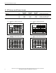
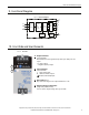
4. Input Inrush Current
A NTC limits the input inrush current after turn-on of the input voltage. The inrush current is input voltage and
ambient temperature dependent.
The charging current into EMI suppression capacitors is disregarded in the rst microseconds after switch-on.
AC 100V AC 120V AC 230V
Inrush current max. 17A
peak
21A
peak
40A
peak
40°C ambient, cold start
typ. 14A
peak
16A
peak
32A
peak
40°C ambient, cold start
Inrush energy typ. 0.15A
2
s 0.2A
2
s 1.0A
2
s 40°C ambient, cold start
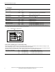
Fig. 4-1 Input inrush current, typical behavior
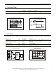
Fig. 4-2 Input inrush current, zoom into rst peak
Input Voltage
Input Current
Output Voltage
Input Current
Input: 230Vac
Output: 24V, 2.5A
Ambient: 25°C
Input current 2A/DIV
Time basis: 0.5ms / DIV
Input: 230Vac
Output: 24V, 2.5A
Ambient: 25°C
Upper curve: Input current 5A/DIV
Middle curve: Input voltage 100V/DIV
Lower curve: Output voltage 5V/DIV
Time basis: 20ms / DIV