
Reference Manual Instruction Manual

All parameters are specified at 24V, 2.5A, 230Vac input, 25°C ambient and after a 5 minutes run-in time, unless noted otherwise.
4 Rockwell Automation Publication 1606-RM007A-EN-P - February 2014
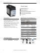
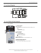
Bulletin 1606 Switched Mode Power Supplies
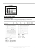
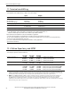
3. AC-Input
AC input nom. AC 100-240V -15% / +10%, TN/TT/IT-mains
AC input range
85-264Vac continuous operation, reduce output power linearly
to 50W between 90Vac and 85Vac at ambient
temperatures above +45°C, see Fig. 3-5
264–300Vac < 0.5s
Allowed voltage L or N to earth max. 264Vac or 375Vdc
Input frequency nom. 50–60Hz ±6%
Turn-on voltage typ. 65Vac
Shut-down voltage typ. see Fig. 3-1
AC 100V AC 120V AC 230V
Input current (rms) typ. 1.14A 0.98A 0.58A at 24V, 2.5A see Fig. 3-3
Power factor *) typ. 0.61 0.58 0.50 at 24V, 2.5A see Fig. 3-4
Crest factor **) typ. 3.2 3.3 3.7 at 24V, 2.5A
Start-up delay typ. 170ms ***) 110ms ***) 90ms see Fig. 3-2
Rise time typ. 50ms 50ms 60ms at 24V, 2.5A, 0mF, see Fig. 3-2
120ms 110ms 140ms at 24V, 2.5A, 2.5mF
Turn-on overshoot max. 200mV 200mV 200mV see Fig. 3-2
*) The power factor is the ratio of the true (or real) power to the apparent power in an AC circuit.
**) The crest factor is the mathematical ratio of the peak value to RMS value of the input current waveform.
***) At low temperatures, start-up attempts may occur which extends the start-up delay.
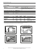
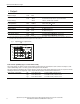
Fig. 3-1 Input voltage range Fig. 3-2 Turn-on behavior, denitions
85
Rated
input range
max.
500ms
V
IN
V
OUT
300Vac26465
Start-up
delay
Rise
Time
Overshoot
- 5%
Output
Voltage
Input
Voltage
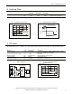
Fig. 3-3 Input current vs. output load at 24V Fig. 3-4 Power factor vs. output load at 24V
2.5A
0.5 1.50
0
0.4
1.2A
Input Current, typ.
2.0
0.8
1.0
1.0
0.6
0.2
b
c
a
a) 100Vac
b) 120Vac
c) 230Vac
Output Current
2.5A
0 0.5 1.0 2.0
0.40
0.45
0.50
0.55
0.60
0.65
Power Factor, typ.
a) 100Vac
b) 120Vac
c) 230Vac
b
c
a
1.5
Output Current