
Reference Manual
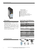
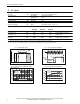
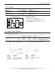
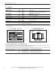
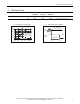
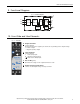
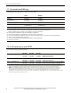
Table Of Contents
All parameters are specified at 24V, 0.63A, 230Vac input, 25°C ambient and after a 5 minutes run-in time, unless noted otherwise.
Rockwell Automation Publication 1606-RM004A-EN-P - January 2014 9
Bulletin 1606 Switched Mode Power Supplies
9. Functional Diagram
Fig. 9-1 Functional diagram
Input Fuse
&
Input Filter
L
N
Output Over-
Voltage
Protection
Input
Rectier
&
Inrush
Limiter
Power
Converter
Output
Voltage
Regulator
+
-
-
Output
Filter
V
OUT
DC
on
PE
10. Front Side and User Elements
Fig. 10-1 Front side
A
Output Terminals
Screw terminals,
Dual terminals for the negative pole allows an easy earthing of the output voltage
+ Positive output
- Negative (return) output
B
Input Terminals
Screw terminals
L Phase (Line) input
N Neutral conductor input
PE (Protective Earth) input
C
DC-on LED (green)
On when the voltage on the output terminals is > 19V
D
Output voltage potentiometer
Turn to set the output voltage. Factory set: 24.5V
POWER SUPPLY
1606-XLP15E
1606-XLP
L
AC 100-240V
N
24 -
28V
DC ok
+
DC 24-28V 15W
Allen-Bradley
IND.CONT.EQ.
18WM
C
D