
Reference Manual Owner's manual

All parameters are specified at 5V, 3A, 230Vac, 25°C ambient and after a 5 minutes run-in time unless noted otherwise.
Rockwell Automation Publication 1606-RM019A-EN-P — March 2014 5
Bulletin 1606 Switched Mode Power Supplies
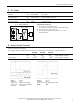
4. DC Input
DC input nom. DC 110-300V -20%/+25%
DC input range min. 88-375Vdc continuous operation
DC input current typ. 0.16A / 0.057A 110Vdc / 300Vdc, at 5V, 3A
Turn-on voltage typ. 80Vdc steady state value
Shut-down voltage typ. 60Vdc steady state value
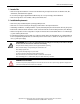
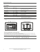
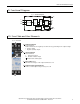
Fig. 4-1 Wiring for DC Input
Instructions for DC use:
+
-
Load
L
N
PE
+
-
Power Supply
AC
DC
Battery
internal
fused
a) Use a battery or similar DC source.
For other sources, please contact Rockwell Automation.
b) Connect +pole to L and –pole to N.
c) Connect the PE terminal to an earth wire or to the
machine ground.
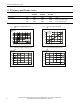
5. Input Inrush Current
A NTC limits the input inrush current after turn-on of the input voltage. The inrush current is input voltage and
ambient temperature dependent.
The charging current into EMI suppression capacitors is disregarded in the rst microseconds after switch-on.
AC 100V AC 120V AC 230V
Inrush current max. 13A
peak
16A
peak
31A
peak
40°C ambient, cold start
typ. 11A
peak
13A
peak
26A
peak
40°C ambient, cold start
Inrush energy max. 0.1A
2
s 0.1A
2
s 0.4A
2
s 40°C ambient, cold start
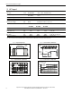
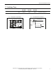
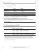
Fig. 5-1 Input inrush current, typical behavior
Fig. 5-2 Input inrush current, zoom into rst peak
Input: 230Vac
Output: 5V, 3A
Ambient: 25°C
Upper curve: Input current 5A/DIV
Lower curve: Input voltage 500V/DIV
Time basis: 10ms / DIV
Output: 5V, 3A
Ambient: 25°C
Input current curve: 5A/DIV, 500μs / DIV
Ipeak 23A