
Manual

Publication GMSI10-UM015B-EN-E - June 2011
Installing the XM Electronic Overspeed Detection System 35
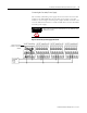
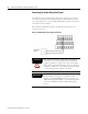
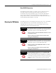
Figure 2.14 Relay Connection - Failsafe, Alarm Condition
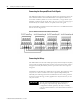
Wiring the XM-220 Relays
The on-board relay in each of the XM-220 modules will serve as the circuit
fault relay for the overspeed channel (channel 1 of XM-220). The alarms
associated with the XM-220 relay and whether the XM-220 relay is normally
de-energized (non-failsafe) or normally energized (failsafe) depends on the
configuration of the XM-220 module.
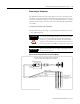
Refer to the XM-220 Dual Speed Module User Guide for relay wiring
illustrations and for a description of the XM-220 configuration parameters.
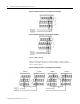
IMPORTANT
To ensure proper operation of the XM EODS, the
on-board relay in each of the XM-220 modules must be
configured for failsafe operation (normally energized).
Refer to Relay Parameters on page 53 for details.
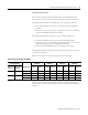
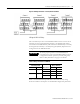
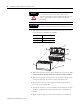
Table 2.2 Relay Connections for XM-220
Configured for
Failsafe Operation Relay 1 Terminals
Nonalarm Alarm Wire Contacts Contact 1 Contact 2
Closed Opened COM 47 50
NO 48 49
Opened Closed COM 47 50
NC 46 51