
Manual

Publication GMSI10-UM015B-EN-E - June 2011
34 Installing the XM Electronic Overspeed Detection System
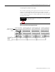
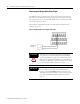
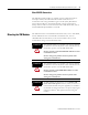
Figure 2.11 Relay Connection - Failsafe, Nonalarm Condition
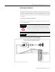
Figure 2.12 Relay Connection - Failsafe, Alarm Condition
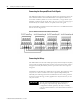
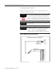
Alternate Relay Wiring
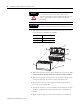
Figures 2.13 and 2.14 show how to wire both ends of a single external
indicator to the XM terminal base for either failsafe, nonalarm condition or
failsafe, alarm condition.
Figure 2.13 Relay Connection - Failsafe, Nonalarm Condition