
Manual

Publication GMSI10-UM015B-EN-E - June 2011
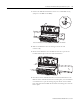
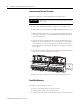
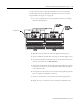
Installing the XM Electronic Overspeed Detection System 27
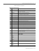
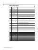
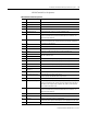
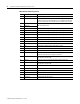
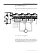
XM-220 Terminal Block Assignments
XM-220 Terminal Block Assignments
No. Name Description
0 Xducer 1 (+) Transducer 1 connection
1 Xducer 2 (+) Transducer 2 connection
2 Buffer 1 (+) Signal 1 buffered output
3 Buffer 2 (+) Signal 2 buffered output
4 Switched Buffer (+) Switched buffered output for use with redundant mode
5 Buffer Power 1 IN Channel 1 buffer power input
Connect to terminal 6 for positive biased transducer or terminal 21 for
negative biased transducer
6 Positive Buffer Bias Provides positive (-5V to +24V) voltage compliance to buffered outputs
Connect to terminals 5 (CH 1) and 22 (CH 2) for positive bias transducers
7 TxD PC serial port, transmit data
8 RxD PC serial port, receive data
9
XRTN
1
Circuit return for TxD and RxD
10 Chassis Connection to DIN rail ground spring or panel mounting hole
11 4-20mA 1 (+) 4-20mA output
300 ohm maximum load
12 4-20mA 1 (-)
13 Chassis Connection to DIN rail ground spring or panel mounting hole
14 Chassis Connection to DIN rail ground spring or panel mounting hole
15 Chassis Connection to DIN rail ground spring or panel mounting hole
16
Xducer 1 (-)
1
Transducer 1 connection
17
Xducer 2 (-)
1
Transducer 2 connection
18
Buffer Common
1
Buffered output return
19 Overspeed/Circuit Fault Overspeed and circuit fault output signal
Used as input by the XM-442 EODS Relay module
20 Switched Buffer (-) Switched buffered output for use with redundant mode (inverted signal)
21 Buffer/Xducer Pwr (-) Provides negative (-24V to +9V) voltage compliance to buffered outputs
Connect to terminals 5 (CH 1) and 22 (CH 2) for negative bias transducers
Transducer power supply output, negative side; used to power external
sensors (40mA maximum load)
22 Buffer Power 2 IN Channel 2 buffer power input
Connect to terminal 6 for positive biased transducer or terminal 21 for
negative biased transducer
23 CAN_High DeviceNet bus connection, high differential (white wire)
24 CAN_Low DeviceNet bus connection, low differential (blue wire)
25 +24V Out Internally connected to 24V In 1 (terminal 44)
Used to daisy chain power if XM modules are not plugged into each other
26 DNet V (+) DeviceNet bus power input, positive side (red wire)