
Manual

Publication GMSI10-UM015B-EN-E - June 2011
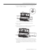
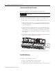
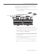
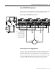
26 Installing the XM Electronic Overspeed Detection System
27 Shutdown Relay 3
Common 1
Shutdown Relay #3 Common contact 1
28 Alarm Relay Common 2 Alarm Relay Common contact 2
29 Alarm Relay Common 1 Alarm Relay Common contact 1
30 No Connection
31 Chassis Connection to DIN rail ground spring or panel mounting hole
32 No Connection
33 No Connection
34 Secondary Power Monitor Connection to secondary external +24V power supply, positive side; used
to monitor the secondary electronic overspeed detection system power
supply
35 Overspeed/Circuit Fault 1 Overspeed and circuit fault input signal #1
Connect to terminal 19 on the first XM-220 module to indicate circuit fault
or alarm (overspeed) condition on channel 1
36 Overspeed/Circuit Fault 2 Overspeed and circuit fault input signal #2
Connect to terminal 19 on the second XM-220 module to indicate circuit
fault or alarm (overspeed) condition on channel 2
37 Overspeed/Circuit Fault 3 Overspeed and circuit fault input signal #3
Connect to terminal 19 on the third XM-220 module to indicate circuit
fault or alarm (overspeed) condition on channel 3
38 Shutdown Relay 1 N.C. 2 Shutdown Relay #1 Normally Closed contact 2
39 Shutdown Relay 1 N.C. 1 Shutdown Relay #1 Normally Closed contact 1
40 Shutdown Relay 2 N.C. 2 Shutdown Relay #2 Normally Closed contact 2
41 No Connection
42 Shutdown Relay 2 N.C. 1 Shutdown Relay #2 Normally Closed contact 1
43 Shutdown Relay 3 N.C. 2 Shutdown Relay #3 Normally Closed contact 2
44 No Connection
45 Shutdown Relay 3 N.C. 1 Shutdown Relay #3 Normally Closed contact 1
46 Alarm Relay N.C. 2 Alarm Relay Normally Closed contact 2
47 Alarm Relay N.C. 1 Alarm Relay Normally Closed contact 1
48 No Connection
49 Chassis Connection to DIN rail ground spring or panel mounting hole
50 No Connection
51 No Connection
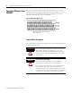
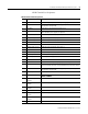
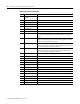
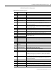
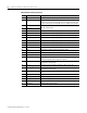
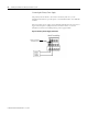
XM-442 Terminal Block Assignments
No. Name Description