
Manual

Publication GMSI10-UM015B-EN-E - June 2011
Installing the XM Electronic Overspeed Detection System 25
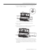
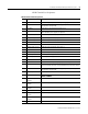
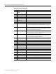
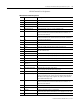
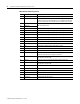
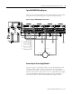
XM-442 Terminal Block Assignments
XM-442 Terminal Block Assignments
No. Name Description
0 24V In 1 Connection to primary external +24V power supply, positive side
1 24V Common Connection to external +24V power supply, negative side (internally
DC-coupled to circuit ground)
2 Reset Relay Switch input to reset internal relay (active low)
3 24V In 2 Connection to secondary external +24V power supply, positive side; used
when redundant power supplies are required
4 Shutdown Relay 1 N.O. 2 Shutdown Relay #1 Normally Open contact 2
5 Shutdown Relay 1 N.O. 1 Shutdown Relay #1 Normally Open contact 1
6 Shutdown Relay 2 N.O. 2 Shutdown Relay #2 Normally Open contact 2
7 No Connection
8 Shutdown Relay 2 N.O. 1 Shutdown Relay #2 Normally Open contact 1
9 Shutdown Relay 3 N.O. 2 Shutdown Relay #3 Normally Open contact 2
10 No Connection
11 Shutdown Relay 3 N.O. 1 Shutdown Relay #3 Normally Open contact 1
12 Alarm Relay N.O. 2 Alarm Relay Normally Open contact 2
13 Alarm Relay N.O. 1 Alarm Relay Normally Open contact 1
14 No Connection
15 Chassis Connection to DIN rail ground spring or panel mounting hole
16 Primary Power Monitor Connection to primary external +24V power supply, positive side; used to
monitor the primary electronic overspeed detection system power supply
17 24V Common Connection to external +24V power supply, negative side (internally
DC-coupled to circuit ground)
18 Reset Relay RTN Reset relay switch return
19 24V Out Diode-ORed output for 24V In 1 and 24V In 2
DO NOT CONNECT
20 Shutdown Relay 1
Common 2
Shutdown Relay #1 Common contact 2
21 Shutdown Relay 1
Common 1
Shutdown Relay #1 Common contact 1
22 Shutdown Relay 2
Common 2
Shutdown Relay #2 Common contact 2
23 No Connection
24 Shutdown Relay 2
Common 1
Shutdown Relay #2 Common contact 1
25 Shutdown Relay 3
Common 2
Shutdown Relay #3 Common contact 2
26 No Connection