User Guide XM Electronic Overspeed Detection System Catalog Numbers XM-442, XM-220, 1606-XLP
Important User Information Solid-state equipment has operational characteristics differing from those of electromechanical equipment. Safety Guidelines for the Application, Installation and Maintenance of Solid State Controls (publication SGI-1.1 available from your local Rockwell Automation sales office or online at http://www.rockwellautomation.com/literature/) describes some important differences between solid-state equipment and hard-wired electromechanical devices.
European Communities (EC) Directive Compliance If this product has the CE mark it is approved for installation within the European Union and EEA regions. It has been designed and tested to meet the following directives.
Rockwell Automation Publication GMSI10-UM015B-EN-E - June 2011
Table of Contents Chapter 1 Introduction Introducing the Electronic Overspeed Detection System . . . . . . . . . . . 7 XM Module Components . . . . . . . . . . . . . . . . . . . . . . . . . . . . . . . . . . . . 9 XM-220 Module Components . . . . . . . . . . . . . . . . . . . . . . . . . . . . . 9 XM-442 Module Components . . . . . . . . . . . . . . . . . . . . . . . . . . . . 10 Using this Manual. . . . . . . . . . . . . . . . . . . . . . . . . . . . . . . . . . . . . . . . . . 10 Organization. . . . . .
Table of Contents Chapter 3 Configuring the XM EODS Configuration Overview . . . . . . . . . . . . . . . . . . . . . . . . . . . . . . . . . . . . 47 Using the XM Serial Configuration Utility . . . . . . . . . . . . . . . . . . . . . . 49 Tachometer Parameters. . . . . . . . . . . . . . . . . . . . . . . . . . . . . . . . . . 50 Alarm Parameters. . . . . . . . . . . . . . . . . . . . . . . . . . . . . . . . . . . . . . . 52 Relay Parameters . . . . . . . . . . . . . . . . . . . . . . . . . . . . . . .
Chapter 1 Introduction This chapter provides an overview of the XM Electronic Overspeed Detection System. It also discusses the components of the Electronic Overspeed Detection System.
Introduction The XM EODS is comprised of the following components: • Two Allen-Bradley™ 1606-XLP30E Power Supplies - The two power supply modules (85 - 264 VAC input, +24V DC output) provide redundant power to the EODS. Each power supply is independently capable of supplying power for the entire system. If one of the power supply modules fails, the system will continue to operate properly.
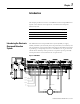
Introduction 9 The XM EODS can operate stand-alone, or it can be deployed on a standard or dedicated DeviceNet network where it can provide real-time data and system information to other XM modules, Programmable Logic Controllers (PLCs), distributed control systems (DCS), and Condition Monitoring Systems. XM Module Components The XM modules in the XM EODS consist of a terminal base and an instrument module. The instrument module and terminal base for the XM-220 and XM-442 is shown below.
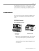
Introduction XM-442 Module Components Figure 1.3 XM-442 Module Components VOTED EODS RELAY XM-946 EODS Relay Terminal Base Unit Cat. No. 1440-TB-G 1440-REX03-04RG XM-442 Voted EODS Relay Module Cat. No. 1440-REX03-04RG • XM-946 EODS Relay Terminal Base Unit - A DIN rail mounted base unit that provides terminations for all field wiring required by the XM-442. • XM-442 Voted EODS Relay Module - Mounts on the XM-946 terminal base unit via a keyswitch and a 96-pin connector.
Introduction 11 Chapter 2 "Installing the XM Electronic Overspeed Detection System" describes how to install, wire, and operate the XM EODS. Chapter 3 "Configuring the XM EODS" provides information to help you configure your XM Electronic Overspeed Detection System using the XM Serial Configuration Utility software. Appendix A "Specification" lists the technical specifications for the XM-442 Voted EODS Relay module. For definitions of terms used in this Guide, see the Glossary at the end of the Guide.
Introduction Publication GMSI10-UM015B-EN-E - June 2011
Chapter 2 Installing the XM Electronic Overspeed Detection System This chapter discusses how to install and wire the XM Electronic Overspeed Detection System. It also describes the LED indicators and the basic operation of the XM EODS.
Installing the XM Electronic Overspeed Detection System XM Installation Requirements This section describes wire, power, and grounding requirements for an XM system. Wiring Requirements Use solid or stranded wire. All wiring should meet the following specifications: • 12 to 28 AWG copper conductors without pretreatment; 8 AWG required for grounding the DIN rail for electromagnetic interference (emi) purposes • Recommended strip length 8 millimeters (0.
Installing the XM Electronic Overspeed Detection System 15 Figure 2.1 is an illustration of wiring modules using separate power connections. Figure 2.
Installing the XM Electronic Overspeed Detection System Figure 2.
Installing the XM Electronic Overspeed Detection System 17 Figure 2.3 DIN Rail Grounding Block To Earth Ground AWG 8 Wire Din Rail Grounding Block Cat. No. 1492-WG10 Panel/Wall Mount Grounding The XM modules can also be mounted to a conductive mounting plate that is grounded. See Figure 2.5. Use the grounding screw hole provided on the terminal base to connect the mounting plate the Chassis terminals. Figure 2.4 Grounding Screw on XM Terminal Base Screw hole for panel/wall mounting.
Installing the XM Electronic Overspeed Detection System Figure 2.5 Panel/Wall Mount Grounding 1 Power Supply 1 Power Supply 1 Publication GMSI10-UM015B-EN-E - June 2011 Use 14 AWG wire. If it is desired to isolate the power supply because of possible ground loops, do not connect 24V Common to earth as illustrated in Figure 2.2. When the 24V supply is isolated from earth, it is recommended to use an isolator on the RS-232 lines. Refer to the XM-220 Dual Speed Module User Guide.
Installing the XM Electronic Overspeed Detection System 19 24V Common Grounding It is recommended that all 24V power to the XM modules is grounded. When two or more power supplies power the XM system, ground the 24V Commons at a single point, such as the ground bus bar. For applications where redundant power supplies are used, only one power supply needs to be grounded. The XM module ties the two 24V Common lines together. IMPORTANT The 24V Common and Signal Common terminals are internally connected.
Installing the XM Electronic Overspeed Detection System Mounting the Terminal Base Units The XM family includes several different terminal base units to serve all of the measurement modules. • The XM-941 terminal base, Cat. No. 1440-TB-B, is the only terminal base unit used with the XM-220 module. • The XM-946 terminal base, Cat. No. 1440-TB-G, is the only terminal base unit used with the XM-442 module. The terminal base can be DIN rail or wall/panel mounted.
Installing the XM Electronic Overspeed Detection System 21 1. Position the XM-946 terminal base on the 35 x 7.5mm DIN rail (A) (A-B pt no. 199-DR1 or 199-DR4). Position terminal base at a slight angle and hook over the top of the DIN rail. 2. Slide the terminal base unit over leaving room for the side connector (B). 3. Rotate the terminal base onto the DIN rail with the top of the rail hooked under the lip on the rear of the terminal base. 4.
Installing the XM Electronic Overspeed Detection System Interconnecting Terminal Base Units Follow the steps below to install the XM-941 terminal base units. IMPORTANT Make certain you install the terminal base units in order of left to right. 1. Position the XM-941 terminal base on the 35 x 7.5mm DIN rail (A). 2. Make certain the side connector (B) is fully retracted into the base unit. 3. Slide the terminal base unit over tight against the neighboring terminal base.
Installing the XM Electronic Overspeed Detection System 23 Use the following steps to install the terminal base on a wall or panel. We recommend you mount the XM-946 terminal base first, next to the power supply modules (see Figure 2.7 on page 29). 1. Lay out the required points on the wall/panel as shown in the drilling dimension drawing below. Side Connector 2. Drill the necessary holes for the #6 self-tapping mounting screws. 3. Secure the XM-946 terminal base unit using two #6 self-tapping screws.
Installing the XM Electronic Overspeed Detection System Connecting Wiring for Your XM EODS Wiring to the module is made through the terminal base unit on which the module mounts. The XM-220 is compatible only with the XM-941 terminal base unit, Cat. No. 1440-TB-B. The XM-442 is compatible only with the XM-946 terminal base unit, Cat. No. 1440-TB-G. Figure 2.6 XM Terminal Base Unit XM-941 (Cat. No. 1440-TB-B) and XM-946 (Cat. No.
Installing the XM Electronic Overspeed Detection System 25 XM-442 Terminal Block Assignments XM-442 Terminal Block Assignments No.
Installing the XM Electronic Overspeed Detection System XM-442 Terminal Block Assignments No.
Installing the XM Electronic Overspeed Detection System 27 XM-220 Terminal Block Assignments XM-220 Terminal Block Assignments No.
Installing the XM Electronic Overspeed Detection System XM-220 Terminal Block Assignments No.
Installing the XM Electronic Overspeed Detection System 29 Typical XM EODS Wiring Diagram Figure 2.7 shows the typical XM Electronic Overspeed Device System wiring configuration. See the following topics for specific wiring information. Figure 2.
Installing the XM Electronic Overspeed Detection System Connecting the Primary Power Supply The primary 24V dc needs to be wired to terminal 0 (24V In 1) on the XM-442 terminal base to provide power to the XM-442 and the other XM-220 modules. Wire the primary power supply to the XM-442 terminal base unit as shown in Figure 2.8. Then place a jumper between terminals 0 and 16 so that the XM-442 can monitor the EODS primary power supply module. Figure 2.
Installing the XM Electronic Overspeed Detection System 31 Connecting the Secondary Power Supply The secondary (redundant) power supply needs to be wired to all of the XM modules in the XM EODS. Wire the secondary power supply to the XM modules as shown in Figure 2.9. Then place a jumper between terminals 3 and 34 on the XM-442 terminal base to enable the XM-442 to monitor the EODS secondary power supply. ATTENTION The power connections are different for the XM-220 and XM-442 modules. Figure 2.
Installing the XM Electronic Overspeed Detection System Connecting the Overspeed/Circuit Fault Signals The XM-442 module accepts one discrete digital input signal from each of the three XM-220 modules. If the XM-220 detects an overspeed condition or a circuit fault condition (failure of a sensor connected to, or logic device in, the XM-220), it will activate this signal. The 1-out-of-3 or 2-out-of-3 voting logic is determined by the number of active overspeed/circuit fault signals.
Installing the XM Electronic Overspeed Detection System 33 Wiring the XM-442 Relays There are four normally energized (failsafe) relays in the XM-442 module. Three relays serve as the shutdown relays. The fourth relay is the alarm relay. The shutdown relays will be activated by any of the following conditions: • Overspeed condition on any two (or all three) of the three XM-220 channels.
Installing the XM Electronic Overspeed Detection System Figure 2.11 Relay Connection - Failsafe, Nonalarm Condition Figure 2.12 Relay Connection - Failsafe, Alarm Condition Alternate Relay Wiring Figures 2.13 and 2.14 show how to wire both ends of a single external indicator to the XM terminal base for either failsafe, nonalarm condition or failsafe, alarm condition. Figure 2.
Installing the XM Electronic Overspeed Detection System 35 Figure 2.14 Relay Connection - Failsafe, Alarm Condition Wiring the XM-220 Relays The on-board relay in each of the XM-220 modules will serve as the circuit fault relay for the overspeed channel (channel 1 of XM-220). The alarms associated with the XM-220 relay and whether the XM-220 relay is normally de-energized (non-failsafe) or normally energized (failsafe) depends on the configuration of the XM-220 module.
Installing the XM Electronic Overspeed Detection System Connecting the Remote Relay Reset Signal The XM-442 relays are latching relays. This means the relays stay activated even when the condition that caused the alarm has ended. The remote relay reset signal enables you to reset the XM EODS relays remotely after you have corrected the alarm condition. Wire the Remote Relay Reset Signal to the XM-442 terminal base unit as shown in Figure 2.15. Figure 2.
Installing the XM Electronic Overspeed Detection System 37 Connecting the Transducers The XM-220 modules can accept input signals from either a proximity probe transducer or magnetic pickup. The three individual transducers are connected to Channel 1 (terminals 0 and 16) of each of the XM-220 modules. For wiring connections pertaining to Channel 2, refer to the XM-220 Dual Speed Module User Guide.
Installing the XM Electronic Overspeed Detection System Connecting a Magnetic Pickup Sensor The figure below shows the wiring of a passive magnetic pickup sensor to Channel 1 of the XM-220 module. ATTENTION IMPORTANT IMPORTANT You may ground the cable shield at either end of the cable. Do not ground the shield at both ends. Recommended practice is to ground the cable shield at the terminal base and not at the transducer.
Installing the XM Electronic Overspeed Detection System 39 Other XM-220 Connections The XM-220 module includes two 4-20mA outputs, a buffered output for each input channel, and a DeviceNet™ connection that allows it to communicate with a Programmable Logic Controller (PLC), Distributed Control System (DCS) or another XM module. It can be connected to a Startup switch as well. For more information about XM-220 module, refer to the XM-220 Dual Speed Module User Guide.
Installing the XM Electronic Overspeed Detection System WARNING IMPORTANT When you insert or remove the XM module while power is on, an electrical arc can occur. This could cause an explosion in hazardous location installations. Be sure that power is removed or the area is nonhazardous before proceeding. Install the XM-220 overlay slide label to protect serial connector and electronics when the serial port is not in use. 1.
Installing the XM Electronic Overspeed Detection System 41 Each XM module has indicators to help you troubleshoot any problems with your XM EODS. The LED indicators are located on top of the module as illustrated in Figure 2.18. LED Indicators Figure 2.
Installing the XM Electronic Overspeed Detection System LED Indicators for the XM-220 Module Each XM-220 module has seven LED indicators – a module status (MS) indicator, a network status (NS) indicator, a status indicator for each channel (CH1 and CH2), an activation indicator for startup, a status indicator for the Relay, and an indicator (AUX) reserved for future use. The following tables describe the status indicators for the XM-220 modules.
Installing the XM Electronic Overspeed Detection System 43 Channel 1 and Channel 2 Indicator Color State Description No color Off • Normal operation within alarm limits on the XM-220 channel. • No power applied to the module, look at XM-220 Module Status LED. Yellow Red Solid An alert level alarm condition exists on the channel (and no transducer fault, tachometer fault, or danger level alarm condition exists).
Installing the XM Electronic Overspeed Detection System Basic Operations Powering Up the Modules Both the XM-220 and the XM-442 perform a self-test at power-up. XM-442 Self-Test The XM-442 self-test includes an LED test. When power is applied to the module, the following occurs. • Module Status (MS) indicator lights red for 1 to 2 seconds and then turns green if it has passed the self-test.
Installing the XM Electronic Overspeed Detection System 45 Manually Resetting the XM EODS Relays The XM-442 has an external reset switch located on top of the module, as shown in Figure 2.19. Figure 2.19 XM-442 Relay Switch 1440-REX03-04RG VOTED EODS RELAY Press the Reset Switch to reset the relays The switch can be used to reset all the latched relays in the XM-442 module. Note that the XM-220 module has an external reset switch as well.
Installing the XM Electronic Overspeed Detection System Publication GMSI10-UM015B-EN-E - June 2011
Chapter 3 Configuring the XM EODS This chapter provides information to help you configure your XM Electronic Overspeed Detection System using the XM Serial Configuration Utility software. Please refer to XM-220 Dual Speed Module User Guide for a complete list and description of the configuration parameters. Descriptions on how to navigate through the software as well as the software screens are contained in the XM Serial Configuration Utility online help.
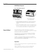
Configuring the XM EODS • Connect the computer to the XM-220 module. Connection to the XM-220 module is through the module’s serial interface using either the three-wire connections on the XM-220 terminal base or the mini-connector on top of the module (see Figure 3.1). Figure 3.1 XM Cable Connection 1440-SPD02-01RB DUAL SPEED Cable connects to the mini-connector on top of the XM-220 module. A special cable (Cat. No. 1440-SCDB9FXM2) is required for the mini-connector connection.
Configuring the XM EODS Using the XM Serial Configuration Utility 49 To configure an XM-220 module using the XM Serial Configuration Utility, follow these steps. 1. Power up the XM-220 module if you haven’t already done so, and start the XM Serial Configuration Utility program. Click the Start program, and then choose Programs > Entek > XM > Serial Config Utility. TIP The Serial Configuration Utility defaults to the COM 1 serial port.
Configuring the XM EODS IMPORTANT If the XM-220 is to be connected to a DeviceNet network and the XM module is set up for Automatic Device Replacement (ADR), you may want to disable the Device >Auto Save Configuration command. For more information about ADR and DeviceNet, refer to Appendix B in the XM-220 Dual Channel Module User Guide. 5. From the File menu, choose Close to close the Configuration Tool window.
Configuring the XM EODS 51 1. In the XM-220 Speed Module Configuration Tool, click the Channel tab. (The Channel tab is the default tab). You will see a screen similar to this. Select Dual channel parameter to ensure proper operation of the XM-220 in the XM EODS. Check this checkbox to cause the XM-220 to provide a a small amount of current to help detect transducer faults for passive magnetic sensors. A voltage reading outside this range constitutes a transducer fault.
Configuring the XM EODS Alarm Parameters Use the Alarm, Relay and 4-20 mA Output tab in the XM-220 Speed Module Configuration Tool to select the type of measurement that is associated with an alarm and to set the alert and danger threshold values. The XM-220 provides a total of eight alarms, four per channel. Each alarm is permanently associated with a particular measurement. To configure the alarm parameters, follow these steps: 1.
Configuring the XM EODS 53 Press F1 to display the online help topic for the current tab or dialog. TIP 4. When you are finished, choose Device > Download to Device to download your changes to the XM-220 module. Relay Parameters Use the Alarm, Relay and 4-20 mA Output tab in the XM-220 Speed Module Configuration Tool to configure which alarms the relay is associated with, as well as the behavior of the relay.
Configuring the XM EODS 2. Select the relay Number that you want to configure. Relay number 1 is the on-board relay (circuit fault relay for XM EODS). Numbers 2 through 5 are either relays on the XM-441 Expansion Relay module when it’s connected to the XM-220 or virtual relays. 3. Enter or select the desired parameters to configure the behavior of the relay.
Configuring the XM EODS 55 1. In the XM-220 Speed Module Configuration Tool, click the Alarm, Relay and 4-20 mA tab. You will see a screen similar to this. This checkbox must be checked in order to enable the 4-20mA output. The measurement and channel that the 4-20mA output tracks. The measured value associated with the 4mA end of the range. The measured value associated with the 20mA end of the range. 2. Select the 4-20 mA output (A or B) that you want to configure. 3.
Configuring the XM EODS View Data from the XM-220 Use the View Data tab to view and analyze live data from the XM-220 module. You can monitor the data, alarms and relays. To view the data from the XM-220, click on the View Data tab in the XM-220 Speed Module Configuration Tool. You will see a screen similar to this. Manually resets a latched relay on the XM-220 module. Resets the maximum speed to zero.
Configuring the XM EODS 57 2. Click the Configure button on the XM Serial Configuration Utility screen. The XM-220 Speed Module Configuration Tool appears. 3. From the File menu, choose Open. The Open dialog appears. 4. Select the saved XM-220 configuration file (.220 file) and click Open. 5. From the Device menu, choose Download to Device. Click the Yes button to download the configuration to the module.
Configuring the XM EODS Publication GMSI10-UM015B-EN-E - June 2011
Appendix A Specifications The Appendix lists the technical specifications for the XM-441 module. Refer to the XM-220 Dual Speed Module User Guide for the technical specifications for the XM-220 module. Refer to the 1606-XLP Power Supply Installation and Operation manual for the technical specifications for the 1606-XLP power supplies.
Specifications XM-441 Technical Specifications Product Feature Specification Relays Number Four relays, two sets of contacts each DPDT (2 Form C) Contacts 250V AC, 50/60 Hz, 3 A Resistive Failsafe Normally energized Latching The shutdown and alarm relays shall latch when the conditions that activate them are met. Voting Logic Two-out-of-three One-out-of-three Activation Low logic level (<0.
Specifications 61 XM-441 Technical Specifications Product Feature Approvals (when product or packaging is marked) Specification UL UL Listed for Ordinary Locations UL UL Listed for Class I, Division 2 Group A, B, C, and D Hazardous Locations CSA CSA Certified Process Control Equipment CSA CSA Certified Process Control Equipment for Class I, Division 2 Group A, B, C, and D Hazardous Locations EEX* European Union 94/9/EEC ATEX Directive, compliant with EN 50021; Potentially Explosive Atmospheres,
Specifications Publication GMSI10-UM015B-EN-E - June 2011
Glossary alarm An alarm alerts you to a change in a measurement. For example, an alarm can notify you when the measured vibration level for a machine exceeds a pre-defined value. Automatic Device Replacement (ADR) A means for replacing a malfunctioning device with a new unit, and having the device configuration data set automatically. The ADR scanner uploads and stores a device’s configuration.
Glossary current configuration The current configuration is the most recently loaded set of configuration parameters in the XM module’s memory. When power is cycled, the current configuration is loaded with either the saved configuration (in EEPROM) or the factory defaults (if there is no saved configuration). In addition, the current configuration contains any configuration changes that have been downloaded to the module since power was applied.
Glossary 65 MAC ID See node address. master device A device which controls one or more slave devices. The XM-440 Master Relay module is a master device. node address A DeviceNet network can have as many as 64 devices connected to it. Each device on the network must have a unique node address between 0 and 63. Node address 63 is the default used by uncommissioned devices. Node address is sometimes called “MAC ID.
Glossary settling time The amount of time it takes a measurement to reach 90% of the final value given a step change in the input signal. slave device A device that receives and responds to messages from a Master device but does not initiate communication. Slave devices include the XM measurement modules, such as the XM-120 Dynamic Measurement module and the XM-320 Position module. transducer A transducer is a device for making measurements.
Index Symbols .
Index M Module Status indicator 41, 42 mounting power supply modules 19 terminal base unit on DIN rail 20 terminal base unit on panel/walll 22 XM module on terminal base 39 N Network Status (NS) indicator 42 normally closed relay contacts 32 normally open relay contacts 32 O opening a previously saved configuration 56 operating mode program mode 42 run mode 42 overspeed/circuit fault signal, wiring 32 XM-220 44 XM-442 44 serial cable 48 Shutdown indicator 41 specifications 59 Startup indicator 43 sw
Index XM Serial Configuration Utility .
Index Publication GMSI10-UM015B-EN-E - June 2011
Rockwell Automation Support Rockwell Automation provides technical information on the Web to assist you in using its products. At http://www.rockwellautomation.com/support/, you can find technical manuals, a knowledge base of FAQs, technical and application notes, sample code and links to software service packs, and a MySupport feature that you can customize to make the best use of these tools.