
Reference Manual Owner's manual
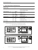
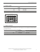
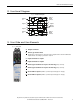
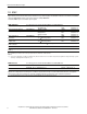
Table Of Contents
All parameters are specified at 24V, 2.5A, 230Vac input, 25ªC ambient and after a 5 minutes run-in time unless noted otherwise.
Rockwell Automation Publication 1606-RM033A-EN-P — March 2014 7
Bulletin 1606 Switched Mode Power Supplies
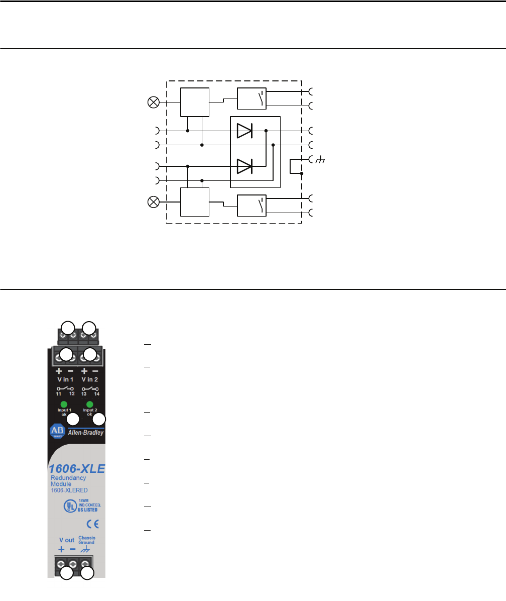
8. Functional Diagram
Fig. 8-1 Functional diagram
+
-
+
-
+
-
Alarm
Relay
Input
Voltage
Monitor
Input 1
Alarm
contact
Alarm
Relay
Input
Voltage
Monitor
Input 2
Alarm
contact
Input 1
ok
Input 2
ok
Input 1
Input 2
Output
Chassis
Ground
9. Front Side and User Elements
Fig. 9-1 Front side
A
Output terminals
B Chassis ground terminal
Connection of the chassis is optional and not required since the unit fulls the
requirements according to protection class III.
C
Input terminals for input 1
D
Input terminals for input 2
E
Alarm-signal terminals for input 1 monitoring (relay contact)
F
Alarm-signal terminals for input 2 monitoring (relay contact)
G
Green LED for input 1 (LED is on, when input voltage is in range)
H
Green LED for input 2 (LED is on, when input voltage is in range)
A
B
C
D
E
F
G
H