
Reference Manual User guide

All parameters are specified at 12V, 2.5A,230Vac input, 25ªC ambient and after a 5 minutes run-in time, unless noted otherwise.
Rockwell Automation Publication 1606-RM030A-EN-P — April 2014 9
Bulletin 1606 Switched Mode Power Supplies
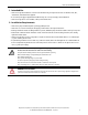
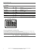
9. Functional Diagram
Fig. 9-1 Functional diagram
+
+
-
-
V
OUT
Output
Over-
Voltage
Protection
PFC
Inductor
Inrush
Limiter
Transient
Filter
Input Fuses
Input Filter
Input
Rectier
Output
Voltage
Regulator
Power
Converter
Output
Filter
Output
Power
Manager
Temper-
ature
Shut-
down
DC-ok
LED
L2
L1
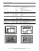
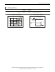
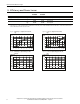
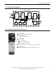
10. Front Side and User Elements
Fig. 10-1 Front side
A
Output Terminals
Screw terminals, dual terminals per pole
+ Positive output
- Negative (return) output
B
Input Terminals
Screw terminals
L1, L2 Phase input
PE (Protective Earth) input
C
Output voltage potentiometer
Open the ap to set the output voltage. Factory set: 12.0V
D
DC-OK LED (green)
On when the voltage on the output terminals is > 10.5V
A
B
C
D